
Integrated self-cleaning window assembly for optical transmission in combustion environments

Inactive Publication Date: 2007-07-24
THE UNITED STATES AS REPRESENTED BY THE DEPARTMENT OF ENERGY
View PDF5 Cites 8 Cited by
  • Summary
  • Abstract
  • Description
  • Claims
  • Application Information

AI Technical Summary

Benefits of technology

[0016]In view of the above need, it is an object of this invention to provide an integrated self-cleaning window assembly that is capable of preventing and removing the accumulation of particulate matter and gaseous hydrocarbons through a combination of catalysis and / or heat.
[0017]It is an object of this invention to provide a device as in the above object that eliminates or reduces hydrocarbon (or other gaseous emission) condensation.
[0018]It is an object of this invention to provide a device as in the above object that provides good optical transmission into a combustion environment even at low temperatures (e.g. <400° C.).
[0020]Briefly, the present invention is an integrated self-cleaning window assembly suitable for most optical applications in combustion environments. The integrated self-cleaning window assembly comprises a transparent base layer made up of any typical optically transparent material, such as quartz, for allowing photons to pass through, and a catalytic material. The catalytic material acts to prevent contaminants from adhering to, or accumulating on, the transparent base layer when the combustion environment is of sufficient temperature.
[0021]Optionally, the integrated self-cleaning window assembly may comprise a transparent base layer and a means for heating. Heating the transparent base layer offsets the tendency for contaminant particles to adhere to the transparent base layer.
[0022]Optionally, the integrated self-cleaning window assembly may include, in addition to the transparent base layer, both a catalytic material and a means for heating. By incorporating both the catalytic material and a means for heating, the self-cleaning capability of the design is greatly enhanced.

Problems solved by technology

These combustion pollutants are commonly exhausted to the atmosphere where they present a potential hazard to human health and the environment.
Monitoring of combustion processes and subsequent emissions within combustion chambers or their exhausts is extremely difficult because of the rapid build up of hydrocarbons and particulate matter on exposed surfaces within the combustion environment.
These technologies, however, require optical access to the exhaust stream of a combustion environment.
Installation of a plain transparent optical access port or window into some component of the exhaust system would be futile because the build up of hydrocarbons and particulate matter would attach to and cloud the window on a frequent and regular basis.
The response of these devices is dependent on the diffusion rate of oxygen atoms through the zirconia and this diffusion rate is limited due to the required thickness of the zirconia-based electrolyte.
Because these sensors are diffusion limited, they have relatively slow time constants (>150 milliseconds) for producing data.
In addition, since oxygen is the conducting medium, they are limited to the measurement of oxygen and some oxide gases (such as NOx), and therefore cannot be used to directly characterize hydrocarbons and particulate matter.
These sensors also have poor resolution and are unable to measure concentrations below 10 parts-per-million.
The barrier to realizing optical diagnostic measurements lies with the constant fouling of the optical port, or window, due to the continual buildup of hydrocarbons and particulate matter.
In spite of this, the portals nevertheless become contaminated over time and must be periodically cleaned.
Another disadvantage of this technology is that a gas supply must be constantly directed over the portal.
A large percentage of the cost for these systems is associated with this gas usage.
Unfortunately, these detectors can also become contaminated with hydrocarbons and particulate matter and, as a result, must be frequently replaced.
In fact, the accumulation of soot and / or hydrocarbons is considered a serious safety issue, since these detectors are considered unreliable when they become dirty.
Williams' invention, however, would not work in the exhaust stream of a combustion environment because both hydrocarbons and particulate matter adhere too strongly to a surface to be wiped clean via mechanical action.
Also, precision mechanical action would be limited if not impossible inside a combustion chamber, as the intense heat and pressure would interfere with mechanical movement and would likely severely damage any wiper assembly.

Method used


Image

  • Integrated self-cleaning window assembly for optical transmission in combustion environments
  • Integrated self-cleaning window assembly for optical transmission in combustion environments
  • Integrated self-cleaning window assembly for optical transmission in combustion environments

Examples


Embodiment Construction

[0049]In view of the above need, a new invention, an integrated self-cleaning window assembly for optical transmission in combustion environments, was developed. The invention consists of an integrated self-cleaning window assembly suitable for most optical applications.

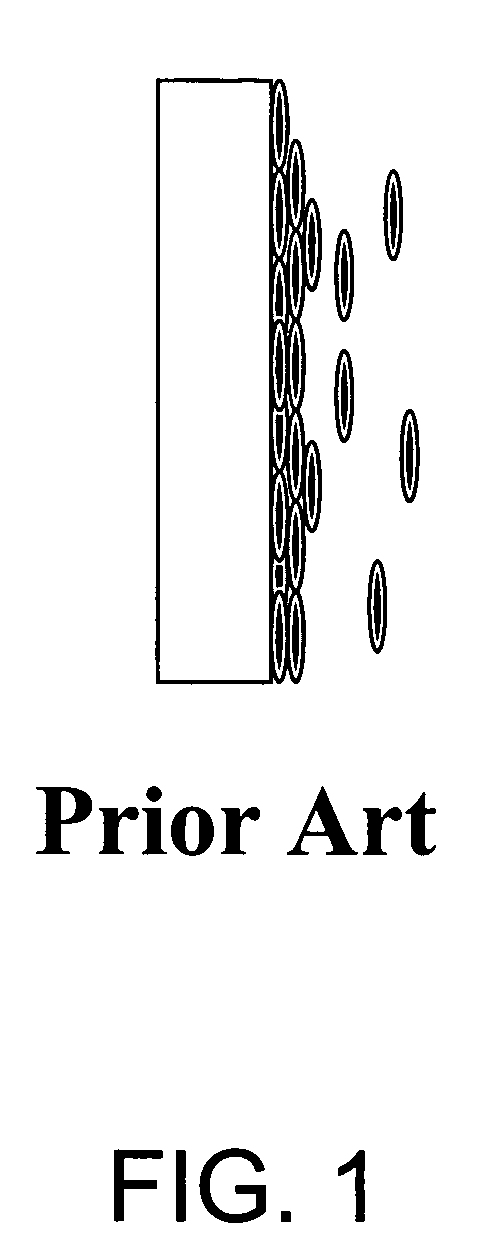
[0050]As shown in FIG. 1, the current state-of-the-art window assembly does not include any means for maintaining optical access if the inner surface becomes fouled with particulate matter or hydrocarbon buildup. FIG. 1 further illustrates how hydrocarbons and particulate matter cling to and collect upon any available surface occurring during combustion within the exhaust stream. Once covered, the current state-of-the-art window assembly becomes useless for effective transmission of an emission sensor beam.

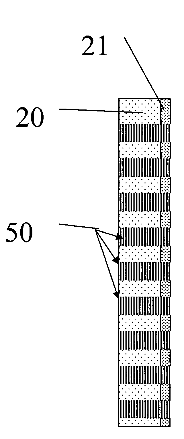
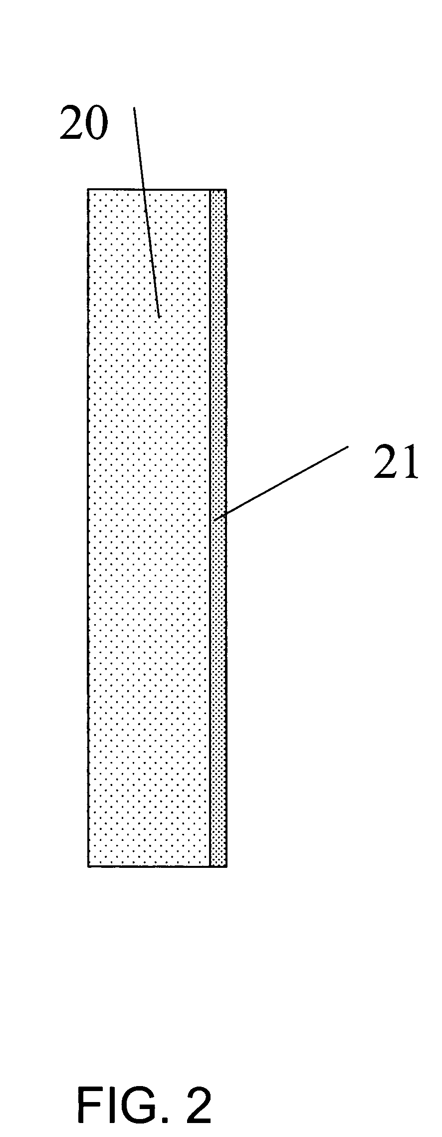
[0051]FIG. 2 illustrates one embodiment of an integrated self-cleaning window assembly. Here, the assembly includes a transparent base layer 20 having an inner and outer surface and a catalytic material 21 laminate...


PUM

PropertyMeasurementUnit
Transparencyaaaaaaaaaa
Heataaaaaaaaaa

Abstract

An integrated window design for optical transmission in combustion environments is described. The invention consists of an integrated optical window design that prevents and removes the accumulation of carbon-based particulate matter and gaseous hydrocarbons through a combination of heat and catalysis. These windows will enable established optical technologies to be applied to combustion environments and their exhaust systems.

Description

[0001]This invention relates to an integrated self-cleaning window assembly for optical transmission in combustion environments. The United States Government has rights to this invention pursuant to Contract No. DE-AC05-00OR22725 with UT-Battelle, LLC, awarded by the U.S. Department of Energy.BACKGROUND OF THE INVENTION[0002]Fossil and renewable energy fuels, such as oil, coal, gas and biomass, are burned or, in other words, combusted in order to produce energy. These combustible fuels may be utilized in internal combustion engines (such as spark ignited and compression ignition systems found in automobiles, trains, ships, planes, and generators), in turbine engines (used to power aircraft and ships), and in furnaces (such as burners, boilers, fluidized beds used in steam power plants).[0003]The burning of combustible fuels to generate energy results in the generation of pollutants including CO, CO2, NOx (NO and NO2), particulate matter, sulfur compounds, and assorted hydrocarbons. ...

Claims


Application Information

Patent Timeline
IPC IPC(8): B32B17/06
CPCC03C17/06C03C17/23C03C17/3417C03C17/36C03C17/3607C03C17/3644C03C17/3649F23M11/04
Inventor KASS, MICHAEL D.PARTRIDGE, JR., WILLIAM P.
Owner THE UNITED STATES AS REPRESENTED BY THE DEPARTMENT OF ENERGY
Learn More