
Insulating glass element, especially for a refrigerated enclosure

a technology of insulating glass and refrigerating enclosure, which is applied in the direction of heater elements, refrigeration devices, building components, etc., can solve the problems of condensation or frost at the periphery of the glazed surface, moisture to the skin, and reduction of the field of vision through, so as to prevent the appearance of condensation

Inactive Publication Date: 2007-07-24
SAINT-GOBAIN GLASS FRANCE
View PDF22 Cites 48 Cited by
  • Summary
  • Abstract
  • Description
  • Claims
  • Application Information

AI Technical Summary

Benefits of technology

[0018]The aim of the present invention is to produce an insulating glazed element formed from at least two glass sheets and at least one section, which makes it possible to prevent the appearance of condensation and the formation of frost on the periphery.
[0019]The invention proposes an insulating glazed element comprising at least two glass sheets and at least one section, said element having at least one heating border on at least one face of at least one glass sheet, and the border being covered by the section and being joined to the section by means of a heat-conducting seal. In this way, by heating the edge of the glazing, it is possible to keep the glass and the section at a temperature greater than the dew point of the ambient air, and therefore to prevent the formation of condensation and of frost on the glass.
[0026]According to a preferred embodiment, the heating border is borne by the external face of the outer glass sheet. In this way, the border is directly in contact, over its entire surface, with the heat-conducting seal, which makes it possible to heat the section with maximum efficiency.
[0031]The length, the width, the thickness and the shape of the border are not critical. In this respect, the invention makes it possible to alter and to optimize the intensity of heating of the border easily: in particular, by varying the width, it is possible to easily obtain parts which are more heated than others within the same strip or several strips. However, it is preferable to choose a shape and a size such that the border may be hidden by the section supporting the glass sheets. Apart from the undeniable esthetic appearance, when the border is borne by the external face of the outer sheet, the covering by the section makes it possible to protect it from subsequent damage such as, for example, that resulting from the application of certain cleaning products.
[0035]In accordance with the second and third embodiments, it is advantageous to combine an intermediate element which can conduct heat with the heating border. This intermediate element may, for example, be a metal sheet, at least one of the ends of which is folded in order to form an angle which is substantially a right angle or a metal L-section or T-section, and one of the ends being connected to the border, for example by welding or bonding, and the other or another free end being placed parallel to the thickness of the glass sheet bearing the border. This method provides a greater area of contact between the border and the heat-conducting seal, which consequently makes it possible to increase the heating efficiency of the section supporting the glass sheets.
[0037]According to a variant of the invention, the outer sheet is a glass sheet having undergone thermal toughening. Thermal toughening makes it possible to generate considerable stresses in the glass such that, when it is broken accidentally, it shatters into fragments which are small enough not to cause injury. The toughening stage is an operation known per se: by way of illustration, it is possible, for example, to carry out the toughening at a temperature of about 550 to 650° C. for 2 to 4 minutes depending on the thickness of the glass. When this sheet bears one or more heating borders in the form of an enamel coating, toughening also makes it possible to cure the enamel.

Problems solved by technology

With chest freezers, and in spite of the use of insulated glazing, there is still the problem of condensation or of frost at the periphery of the glazed surface.
The presence of condensation water or of frost has drawbacks: reduction in the field of vision through the glazed element, appearance of mold, formation of puddles on the ground, transfer of moisture to the skin, the presence of stains on the clothing, the risk of the skin “sticking” to the frosted parts, etc.
However, this bead is not entirely satisfactory:it is minimally adjustable because its length depends entirely on the dimension of the glazing,it is tricky and expensive to implement because it is necessary to make a perfectly gaged groove in the thickness of the seal of the glass sheets,since the contact area between the bead and the frame is small, the heating efficiency is low, andgiven that it is fed by an electric current of high voltage (about 220 volts), a safety device, which breaks the circuit in the case of accidental breakage of the glass, must absolutely be combined therewith.

Method used


Image

  • Insulating glass element, especially for a refrigerated enclosure
  • Insulating glass element, especially for a refrigerated enclosure
  • Insulating glass element, especially for a refrigerated enclosure

Examples


first embodiment

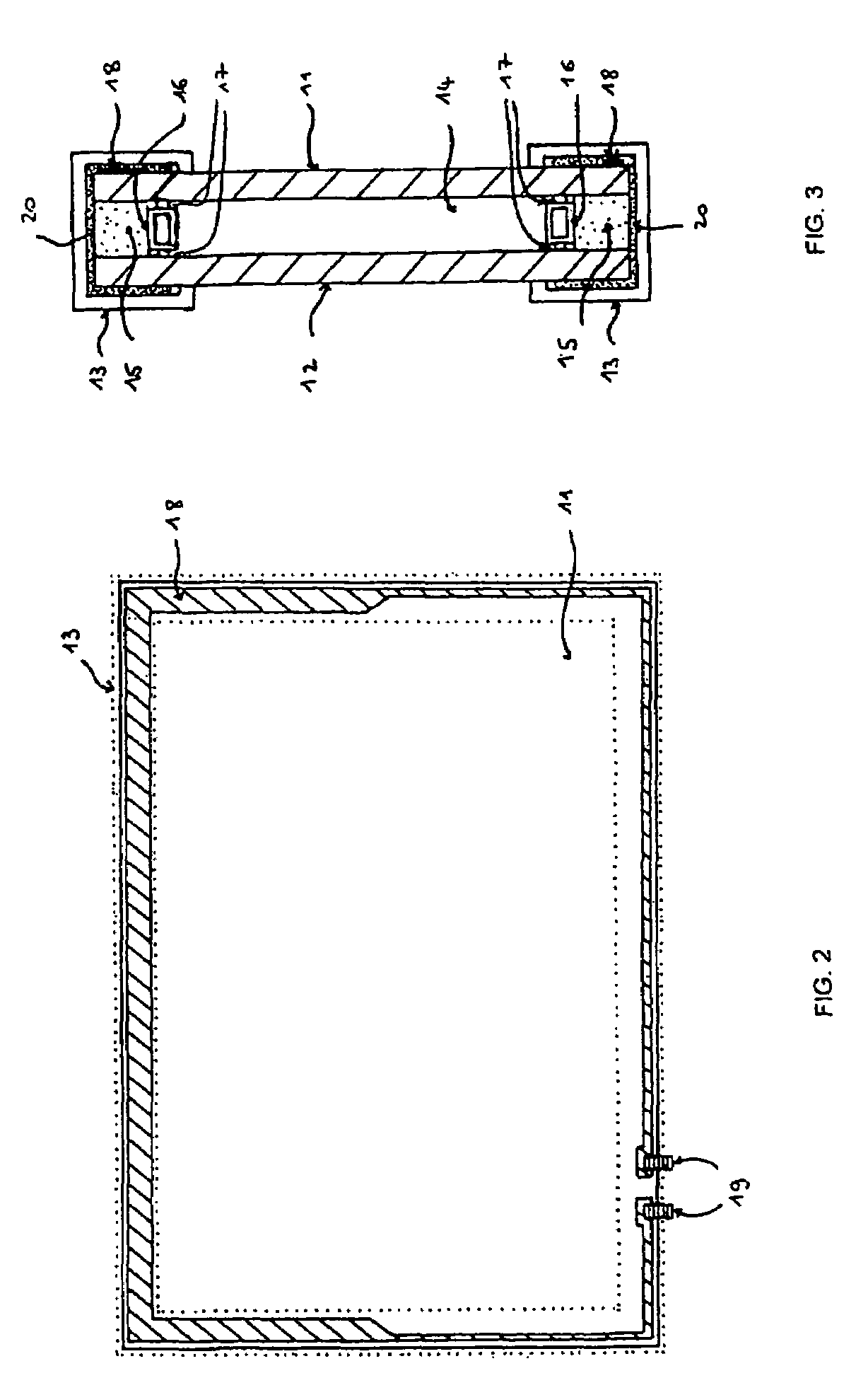
[0047]FIG. 2 shows a front view of a glazed element according to the invention.

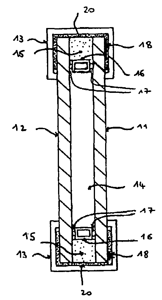
[0048]FIG. 3 is a vertical section through this same element.

[0049]According to this embodiment, the glazed element comprises two glass sheets 11, 12, provided with a heating border 18, supported by a frame having the shape of the section 13. In FIG. 2, the section 13 is represented by dotted lines in order to show the heating border 18 more clearly.

[0050]The glass sheets 11, 12 are separated from each other by a space 14 and joined at the periphery by a seal 15, which is watertight. Into the space 14, at a small distance from the edge of the sheets 11, 12, is inserted a hollow section 16 containing a desiccating agent, which is fixed to the glass by an adhesive bead 17. The outer sheet 11 is provided, on its external face, with a heating border 18 of variable width which extends over the four sides of the sheet, the ends of which bear a terminal 19 for the electrical supply. A heat-conducting seal 20 pro...

second embodiment

[0051]FIG. 4 shows a front view of a glazed element according to the invention and FIG. 5 is a vertical cross section through this element.

[0052]As above, the element consists of glass sheets 11, 12 supported by the section 13, also shown in dotted lines in FIG. 4. The glass sheets 11, 12, separated by the space 14, are joined at the periphery by the seal 15. The space 14 comprises the hollow section 16 containing the desiccating agent and the adhesive bead 17 (not shown). In this case, the outer sheet 11 bears, on the internal face, two different heating borders 21, 22, of the same width and of a length substantially equal to the sides of the sheet 11, the ends of which bear terminals 19. Intermediate elements 23 are attached to the borders 21, 22 by adhesive bonding or by welding at the end 24, the end remaining free 25 itself being folded toward the sheet 11 and lying in a plane substantially parallel to the thickness of the sheet. The entire surface of the end 25 is thus exposed...

third embodiment

[0053]FIG. 6 shows a front view of a glazed element according to the invention and FIG. 7 is a vertical section through this element.

[0054]In this case, the elements consist of three sheets of glass 11, 12, 26 supported by the section 13, also shown in dotted lines in FIG. 6. The glass sheets 11, 12, 26, separated by the spaces 14, 27, are joined at the periphery by the seal 15. Each space 14, 27 contains the hollow section 16 containing the desiccating agent and the adhesive bead 17 (not shown). In this case, the intermediate sheet 12 bears, on the external face, a heating border 28, formed from upper 29 and lower 30 strips connected together at one side, whose ends provided with terminals 19 are located on the side of the sheet away from the previous side.

[0055]In this case, the intermediate element 31 is a T-section, whose web 32 is fastened to the strip 29 of the heating border 28 and whose flanges 33 lie in a plane substantially perpendicular to the plane of the sheet 26 bearin...


PUM


Abstract

An insulating glazed element including at least two glass sheets, separated from each other by a space and joined at their periphery by a seal, and at least one section. The glazed element has at least one heating border on at least one face of at least one glass sheet, and the border is covered by the section and joined to the section by a heat-conducting seal.

Description

BACKGROUND OF THE INVENTION[0001]1. Field of the Invention[0002]2. Discussion of the Background[0003]The invention relates to an insulating glazed element comprising at least two glass sheets separated from each other by a space and at least one support element, especially for a refrigerated enclosure.[0004]Glazing panels are generally placed in a frame making it possible to support them for the purpose of their use in fields where their thermal insulation properties are sought (building, refrigeration, etc.).[0005]It is well known that when a cold wall is in contact with hot and moist air, the wall becomes covered with water from the condensation of the ambient water vapor, it being possible for this water even to become transformed into frost if the temperature is low enough. More specifically, it is when the temperature of the wall is less than the dew point of the ambient air that condensation is produced. In the case of glazing panels, the condensation may appear on the glass a...

Claims


Application Information

Patent Timeline
Patent Type & Authority Patents(United States)
IPC IPC(8): E06B7/00H05B1/00H05B11/00H05B3/00H05B3/06H05B3/84
CPCH05B3/84F25D2201/14A47F3/0434F25D23/065
Inventor BEYRLE, ANDRE
Owner SAINT-GOBAIN GLASS FRANCE
Learn More