Tennis ball delivery device

a technology of tennis ball and ball carrier, which is applied in the direction of racket sports, ammunition loading, sports apparatus, etc., can solve the problems of limiting use, not easy to carry, and large weight, and achieves the effects of convenient portability, convenient strike, and economic manufactur

Inactive Publication Date: 2007-07-17
IDEABOY
View PDF12 Cites 11 Cited by
  • Summary
  • Abstract
  • Description
  • Claims
  • Application Information

AI Technical Summary

Benefits of technology

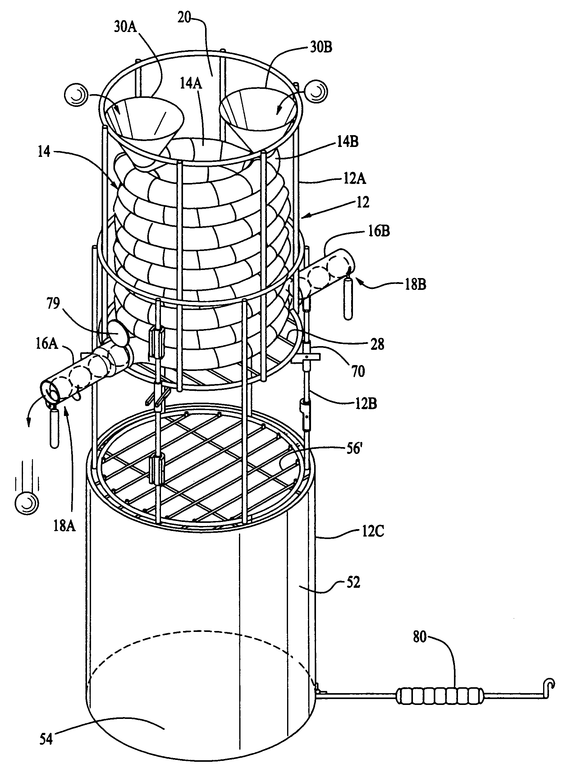
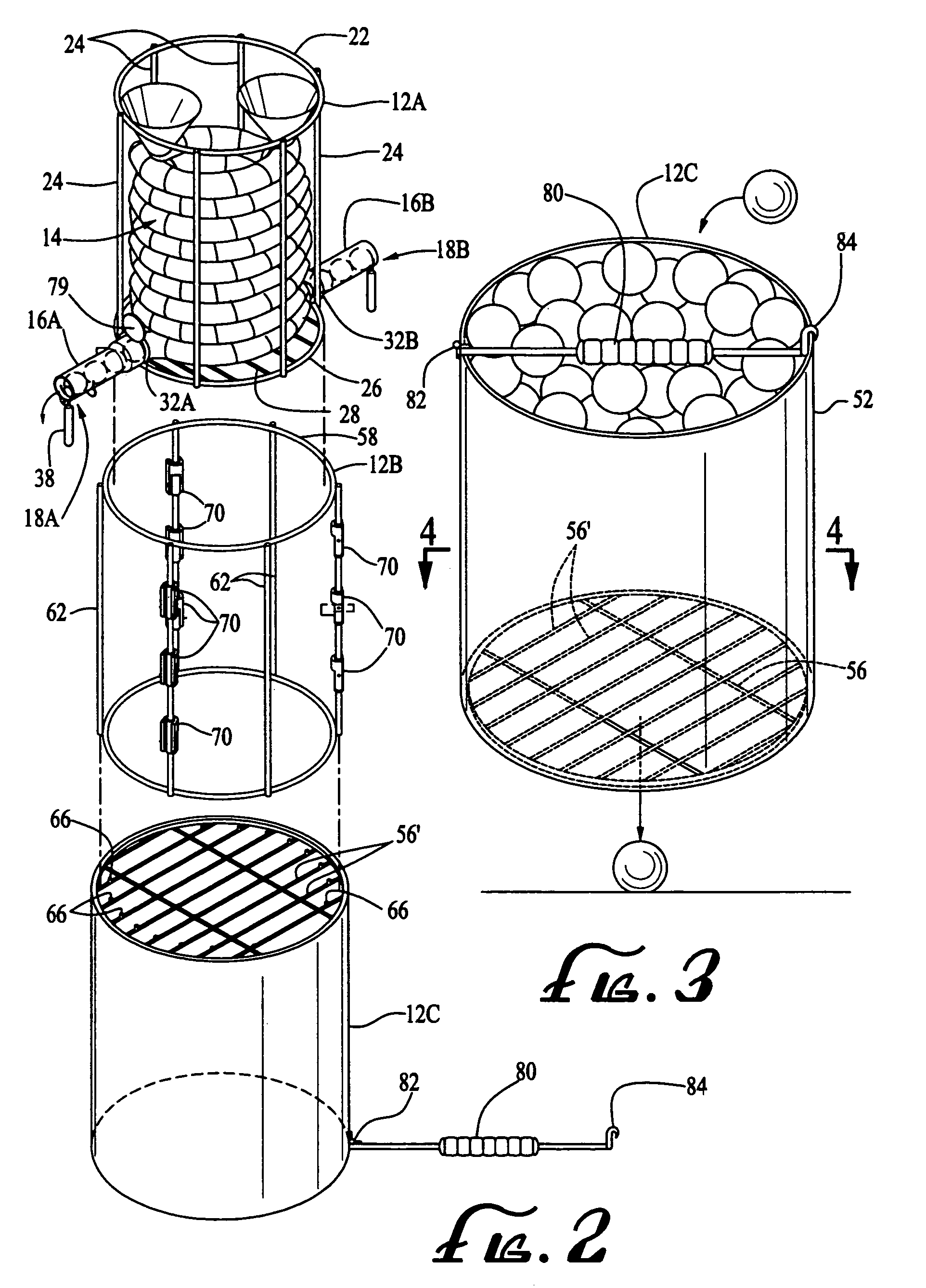
[0004]Briefly, the present invention comprises a tennis ball delivery device for use in practicing one's tennis stroke that obviates the need to retrieve a new ball after each stroke, is very economical to manufacture and is readily portable. The device carries a supply of tennis balls and, upon activation, drops a single ball from a selected and variable elevation so that the ball will bounce to a desired height where it can be struck by the player using either a forehand or a backhand stroke. In its preferred embodiment, the device comprises an adjustable and collapsible frame assembly, a pair of ball supply conduits carried in an upper portion of the assembly and a ball release mechanism carried by each of the lower outlet ends of the conduits, which project outwardly in opposed directions from the frame. The release mechanisms preferably employs a depending handle that can be easily struck by the player with his or her racket so as to effect the release of a single ball from the elevated conduit such that the ball can fall to the ground, bounce upwardly and be struck by the player. The release mechanism includes a stop for preventing more than one ball from falling from the conduit with each movement of the handle. By providing a pair of opposed ball outlets, a person can practice his or her forehand and backhand stroke without having to move the ball delivery device. The frame assembly preferably is formed in detachable sections that allows for varying the elevation of the ball conduit and nesting of the frame sections for portability and storage. One portion of the frame assembly is preferably provided with a wire grid surface that functions as a support surface during use as a ball delivery device, as a bottom flooring for the device in the nested carrying position, and as a ball retrieval device.
[0005]It is therefore the principal object of the present invention to provide a ball delivery device for practicing one's tennis stroke which is highly versatile, of simple construction so as to be economical to manufacture and is readily portable.

Problems solved by technology

Such practice devices are relatively large and heavy and hence not easily portable which limits their use.
They also require electricity and are relatively expensive, particularly for children in poor families and for people in general in less affluent countries who wish to learn the game of tennis.
Because of the size and weight of such devices, they also are not easily used for practice by children and older players without assistance.
Without a ball delivery device, a player or prospective player can only practice his or her strokes with a coach, which is very expensive, by hitting a ball against a wall, which generally does not provide repetitive practice of the same stroke, particularly for a novice, or by repetitively dropping a ball on the same spot and at the same height.
By having to drop the ball and then turn and strike the ball, the player cannot focus on the proper body position prior to and during the stroke.
Also, learning through repetition is impaired because the player has to continually leave his or her position to retrieve another ball.
As a result, the rhythm of repetitive practice is lost.

Method used


Image

  • Tennis ball delivery device
  • Tennis ball delivery device
  • Tennis ball delivery device

Examples


second embodiment

[0040]the present invention is illustrated in FIG. 15. In the tennis ball delivery device 100 illustrated therein, the frame 112 comprises a plurality of telescoping legs (three being shown) 112A, 112B, and 112C joined at their upper ends in a circular support ring 112D. The upper ends of the legs can be permanently secured to the upper support ring by welding or an adhesive suitable for the materials of which the frame is constructed or removeably secured by a threaded engagement or other suitable fastening means. The frame could be constructed of a durable plastic or a metal material. The ability of the legs to telescope allows for variation in the elevation of the ball delivery chute 116. The telescoping function can be provided by conventional threaded clamps 117 that compress a slotted end of an outer leg section about a portion of an inner leg section as illustrated in the drawing. Other telescoping leg configurations could, of course, be employed. For example, a plurality of ...

third embodiment

[0043]the invention is illustrated in FIG. 16. The ball delivery device 200 of FIG. 16 differs from that of FIG. 15 primarily in the design of the frame 212 and the means for activating the ball drop mechanism. As indicated earlier, a wide variety of frame constructions could be employed in the present invention. Frame 212 comprises a single leg comprised of an upper portion 212A and lower portion 212B and a bottom pedestal stand support 213. As with the prior embodiment, a variety of means could be employed to effect the telescoping of the frame 212. A conventional threaded attachment 217 is illustrated in FIG. 16. The remainder of the components of the delivery device 200 are basically identical to those in the above-described device 100 except that the ball delivery device 200 is provided with an automatic delivery chute activator 225. The activator 225 eliminates the need for a player to physically strike the ball release handle as in the prior embodiments. Activator 225 can be ...


PUM


Abstract

A tennis ball delivery device for use in practicing one's tennis stroke. The device includes an adjustable frame, at least one declining ball delivery conduit carried by the frame in an upper portion thereof, a declining ball discharge shoot carried by and communicating with the delivery conduit and a ball release mechanism carried by the discharge conduit. The release mechanism allows a single ball to fall from the shoot in response to the activation thereof. A depending handle that can be easily struck by the player's racket in initiating their tennis stroke is operatively connected to the release mechanism so as to effect the release of the ball.

Description

CROSS-REFERENCE TO RELATED APPLICATIONS[0001]This application claims the benefit of U.S. Provisional Patent Application Ser. No. 60 / 657,952, filed Mar. 2, 2005.BACKGROUND OF THE INVENTION[0002]The present invention relates to a tennis ball delivery device and, more particularly, to a low cost, readily producible and easily portable device for holding a supply of tennis balls that, upon actuation by a player, will deliver a ball to the player for practicing his or her tennis stroke. While a wide variety of practice devices are presently available to tennis players for developing their strokes, they typically comprise devices that drive or shoot a ball over the net toward the player who then returns the ball using a backhand or forehand stroke. The proper tennis strokes and footwork are developed through repetitive practice. Such practice devices are relatively large and heavy and hence not easily portable which limits their use. They also require electricity and are relatively expens...

Claims


Application Information

Patent Timeline
Patent Type & Authority Patents(United States)
IPC IPC(8): A63B69/38
CPCA63B47/002A63B2208/12A63B2243/0083A63B2102/02
Inventor MORSHED, HADIMORSHED, NICHOLAS A.
Owner IDEABOY
Why Eureka
Try Eureka