
Control system for canceling load unbalance of three-phase circuit

a control system and load unbalance technology, applied in emergency protective circuit arrangements, ac network circuit arrangements, air-break switches, etc., can solve problems such as the failure of an over-current grounding relay (ocgr)

Inactive Publication Date: 2007-07-10
MITSUBISHI ELECTRIC CORP
View PDF12 Cites 24 Cited by
  • Summary
  • Abstract
  • Description
  • Claims
  • Application Information

AI Technical Summary

Benefits of technology

[0007]An object of the present invention is to provide a control system for canceling load unbalance of a three-phase circuit which is capable of detecting a change of each single-phase load which is changed from moment to moment to change single-phase loads having respective phases over to one another at a high speed (within one to two cycles or so, i.e., within about 20 to 40 msec), i.e., to change single-phase loads having respective phases over to one another within a very short period of time not causing service interruption for any of consumers to thereby balance the loads when viewed in the form of three-phase loads.
[0010]In the control system for canceling load unbalance of a three-phase circuit according to the present invention, such effects can be obtained that a part of a load of a phase having a maximum current appearing therein can be shifted over to a load of a phase having a minimum current recognized therein to surely cancel unbalance in loads of a three-phase circuit to thereby prevent malfunction of an over-current grounding relay (OCGR).

Problems solved by technology

Then, malfunction of an over-current grounding relay (OCGR) is due to load unbalance among a neutral conductor and loads of a multiple direct grounding series.

Method used


Image

  • Control system for canceling load unbalance of three-phase circuit
  • Control system for canceling load unbalance of three-phase circuit
  • Control system for canceling load unbalance of three-phase circuit

Examples


embodiment 1

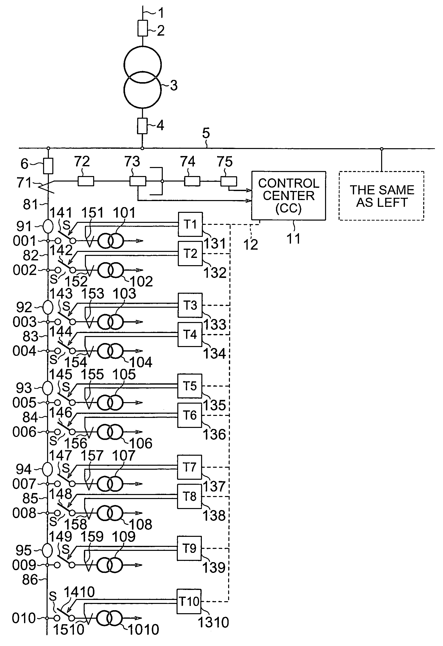
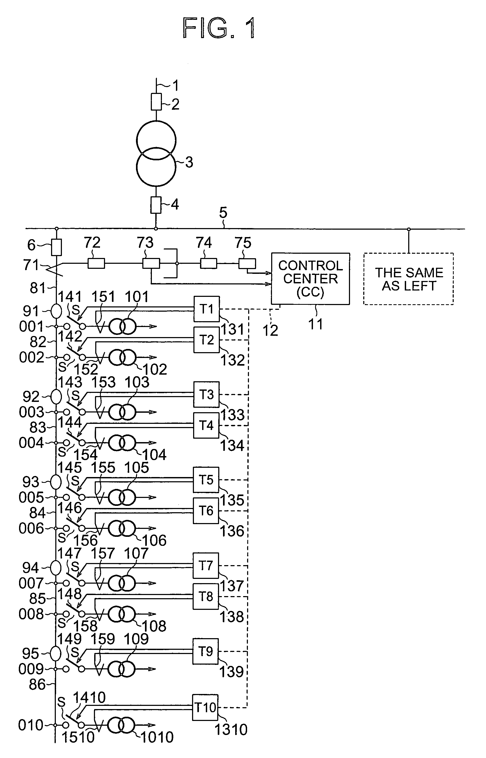
[0026]A control system for canceling load unbalance of a three-phase circuit according to Embodiment 1 of the present invention is described with reference to the accompanying drawings. FIG. 1 is a circuit diagram, partly in block diagram, showing a configuration when a control system for canceling load unbalance of a three-phase circuit according to Embodiment 1 of the present invention is applied to a high voltage power distribution system in a multiple grounding system. Note that, in the figure, the same reference numerals designate the same or corresponding constituent elements.

[0027]In FIG. 1, a receiving line 1 of a distribution station is connected to a receiving circuit breaker 2. A primary side of a main transformer 3 is connected to the receiving circuit breaker 2, and a secondary side thereof is connected to a bank secondary circuit breaker 4. A high voltage bus 5 is connected to the bank secondary circuit breaker 4.

[0028]In addition, in FIG. 1, a feeder circuit breaker 6...


PUM


Abstract

A control system for canceling load unbalance of a three-phase circuit includes phase current detectors for detecting phase currents caused to flow through a secondary circuit of a current transformer provided in high voltage distribution lines, respectively, phase change-over switches through which phases of the high voltage distribution lines, and primary sides of distribution transformers provided across high and low voltage distribution lines are connected to each other, a control center for, when a magnitude of a zero-phase current detected by the zero-phase current detector is larger than a predetermined value, on the basis of the phase currents, respectively, out putting a control signal so that the load of the phase having a maximum current appearing therein is changed over to the phase having a minimum current recognized therein, and a phase change-over slave station for controlling the phase change-over for the phase change-over switches in accordance with the control signal.

Description

BACKGROUND OF THE INVENTION[0001]1. Field of the Invention[0002]The present invention relates a control system for canceling load unbalance of a three-phase circuit which is capable of preventing malfunction of an over-current grounding relay (OCGR) due to load unbalance in multiple direct grounding series distribution lines.[0003]2. Description of the Related Art[0004]A conventional closed circuit protector for a secondary side circuit of a current transformer receives as its input a secondary current of the current transformer to compare the secondary current thus inputted thereto with a predetermined current value within the closed circuit protector to thereby detect that a secondary circuit of the current transformer has been disconnected or opened, to form a closed circuit in the form of a short-circuit (refer to a page 1 and FIG. 1 of Japanese Patent Laid-Open No. 11-205998, for example).[0005]The conventional device as described above has no function of comparing loads of pha...

Claims


Application Information

Patent Timeline
IPC IPC(8): H02J3/26H02H7/26H01H33/66H02H3/34
CPCH02J3/26H01H33/6662Y02E40/50H02H3/34
Inventor MATSUMOTO, TADASHIMITANI, MITSURUTANGE, SEIJI
Owner MITSUBISHI ELECTRIC CORP
Learn More