Fuser roll with improved heating performance

Inactive Publication Date: 2007-07-10
ILLINOIS TOOL WORKS INC
View PDF14 Cites 7 Cited by
  • Summary
  • Abstract
  • Description
  • Claims
  • Application Information

AI Technical Summary

Benefits of technology

[0014]An advantage of the present invention is providing a fuser roll that heats rapidly and evenly to provide uniform surface temperatures during high-speed operation.
[0015]Another advantage of the present invention is providing an improved fuser roll structure that can be manufactured and assembled easily and cost effectively.
[0016]Still another advantage of the present invention is providing a fuser roll that remains reliable in performance over an extended period of time.
[0017]A further advantage of the present invention is providing a fuser roll structure which rapidly distributes heat from hotter areas to colder areas of the fuser roll in both axial and radial directions of the roll.
[0018]A still further advantage of the present invention is providing a fuser roll that promotes heat distribution along the surface thereof using only static components not prone to failure or malfunction.
[0019]Other features and advantages of the invention will become apparent to those skilled in the art upon review of the following detailed description, claims and drawings in which like numerals are used to designate like features.

Problems solved by technology

The surface temperatures become non-uniform, and, before a next piece of media passes through the fuser, the fuser roll must be reheated.
If printing on one size medium is followed immediately by printing of a different size medium, the second medium may receive non-uniform heat applied thereto from the fuser roll unless the reheating process accounts for the non-uniformity of surface temperature following the preceding fusing process.
Since proper fusing of fusible inks is a function of heat residence time and pressure, if the pressure and residence time are the same but the heat applied varies from one part of the medium to another part of the medium, non-uniform fusing can occur.
Under-fused inks can cause smearing, offset and other unacceptable conditions.
However such a delay itself can be unacceptable.
Thus, delaying a subsequent printing function for a different size medium following a first size medium can require unacceptable delay in a high-speed office machine.
However, the heat response time of a heat pipe depends on the outer surface material, and it is often difficult to maintain a very thin outer surface on a heat pipe.
The heat pipe requires a liquid or vapor within the heat pipe, and the assembly is somewhat cumbersome to install and expensive to manufacture.

Method used


Image

  • Fuser roll with improved heating performance
  • Fuser roll with improved heating performance

Examples


Embodiment Construction

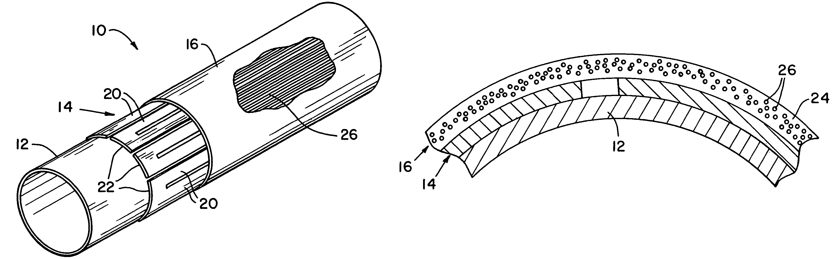
[0023]Referring now more specifically to the drawings and to FIG. 1 in particular, numeral 10 designates a fuser roll constructed in accordance with the present invention. Fuser roll 10 can be used as the heat source in a fuser for an electrophotographic printing process performed in a printer, copier, fax machine, or the like. While the invention is shown and described herein for use and application on a fuser roll, it should be understood that a fuser roll is merely one suitable application fur the present invention. The invention has application and utility for use with heated rolls of other types, and in devices other than printing devices.

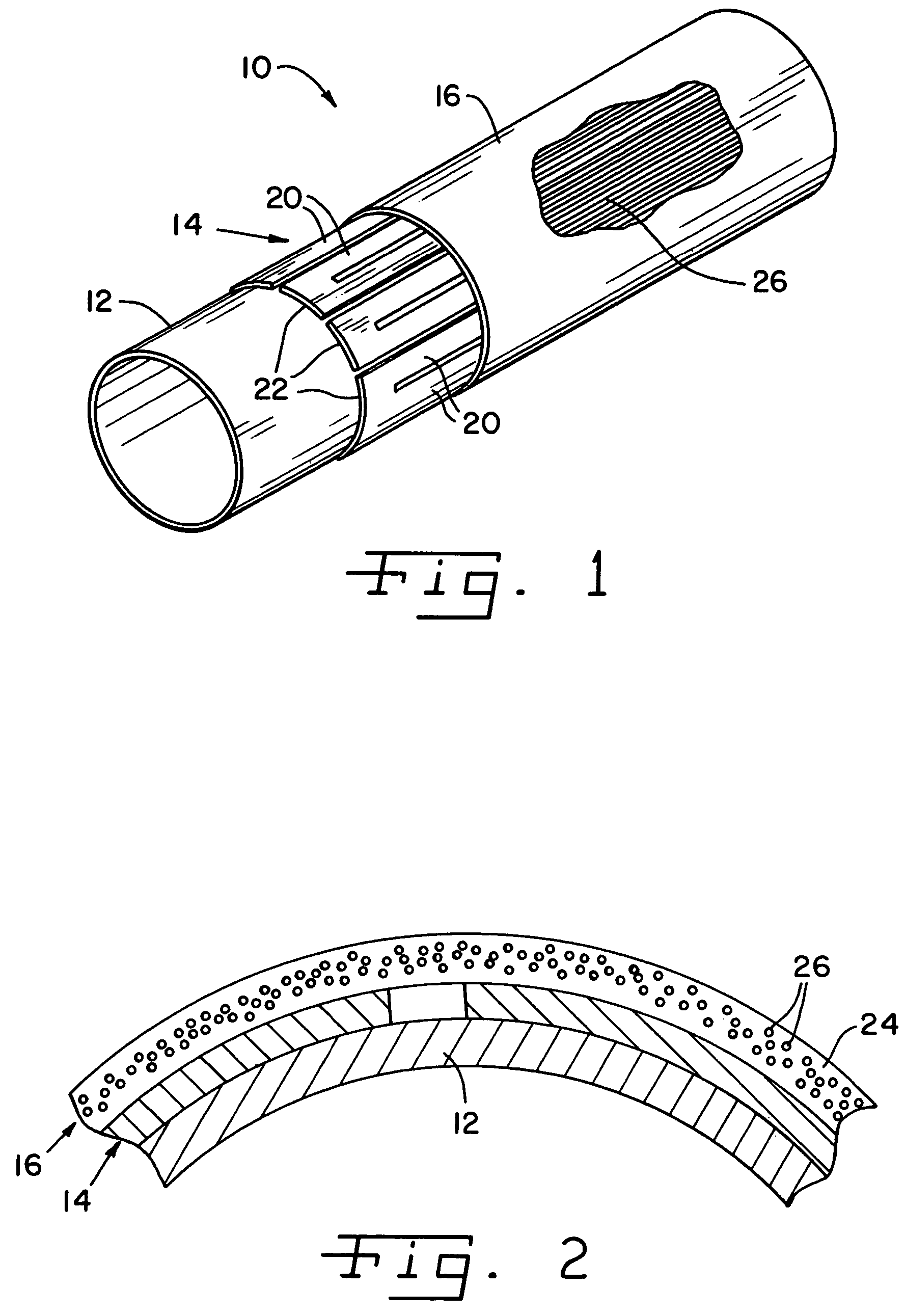
[0024]Fuser roll 10 includes a cylindrical body or shell 12, an intermediate layer 14 and an outer layer 16. Intermediate layer 14 is applied on and bonded to roll body 12, and outer layer 16 is applied to and bonded on intermediate layer 14. Thus, in final construction, fuser roll 10 is a laminated body of applied, bonded layers on body 12.

[0...


PUM


Abstract

A roll cover particularly suitable for a fuser roll has an intermediate layer on the roll body and an outer surface layer including heat transfer bodies therein. The intermediate layer is a graphite sheet having legs extending along the axial extent of the roll body. The outer layer has graphite fibers embedded therein, the graphite fibers extending axially with respect to the roll.

Description

CROSS-REFERENCE TO RELATED APPLICATIONS[0001]The present regular United States Patent Application claims the benefit of United State Provisional Application No. 60 / 446,466 filed on Feb. 11, 2003.FIELD OF THE INVENTION[0002]The present invention relates to heat conductive structures and, more particularly, to fuser rolls in electrophotographic printing applications and structures for improving the uniformity heat conducted through such rolls.BACKGROUND OF THE INVENTION[0003]Many processes use heated rolls in one or more steps of the process. Some require a high degree of heat uniformity on the roll surface, to achieve uniformly acceptable results. As heat is removed from the roll, heat distribution can become transiently non-uniform, and heating the roll preferable will account for the non-uniformity that occurs during use.[0004]For example, printers, copiers and other printing devices commonly use an electrophotographic printing process in which a uniform charge is applied to a phot...

Claims


Application Information

Patent Timeline
IPC IPC(8): F16C13/00B25F5/02G03G15/20
CPCG03G15/2053
Inventor OH, HIEYOUNG W.KING, CHARLES A.
Owner ILLINOIS TOOL WORKS INC
Why Eureka
Try Eureka