Electrical connector with integrated terminal position assurance and wire cover

a technology of integrated terminal position assurance and electrical connector, which is applied in the direction of electrical apparatus, connection, coupling device connection, etc., can solve the problems of increasing the space required for the connector, increasing the difficulty of designing the connector, and the inability to mount the connector in a confined space, so as to reduce the number of wires used, reduce manufacturing complexity or cost, and ensure the effect of assembly precision

Inactive Publication Date: 2007-07-10
GM GLOBAL TECH OPERATIONS LLC +1
View PDF20 Cites 17 Cited by
  • Summary
  • Abstract
  • Description
  • Claims
  • Application Information

AI Technical Summary

Benefits of technology

[0016]The presently inventive electrical conductor defines a connector body forming a cavity therein, one or more terminal carriers which define a plurality of terminal receiving passageways therein which open through an end surface of the terminal carrier. A slide member cooperates with the connector body to positionally fix the terminal carrier with respect thereto. Finally, a wire cover is disposed to substantially overlay the terminal carrier end surface and acts to dress conductors emerging from the openings in a preferred orientation. The wire cover is integrally formed with and depends from the slide member. This arrangement has the advantage of affording precise dressing of the emerging wire bundle without adding to part count, manufacturing complexity or cost.
[0017]According to an aspect of the invention, the wire cover serves to precisely offset the wires emerging from the terminal carrier passageways. This arrangement allows preassembly and pre-dressing of the wires prior to final installation and to avoid nearby obstructions.
[0018]According to another aspect of the invention, the wire cover can be configured to selectively dress subsets of wires emerging from the terminal carrier passageways in two or more discrete orientations. The advantage of this arrangement is that each wire can be directed or routed immediately toward its intended interconnection circuit element to minimize wire used while protecting it from adjacent obstructions.
[0019]According to yet another aspect of the invention, a second slide member is disposed substantially parallel with the first slide member. Both slide members are integrally formed with the wire cover and each is separately engagable with the connector body, resulting in an extremely robust design, which can provide strain relief for the wire bundles.

Problems solved by technology

However, in order to ensure proper installation, various complexities must be taken into account.
Use of a CPA may lead to further difficulties when designing a connector.
An external CPA may increase the space required for the connector, so that a CPA may be unavailable for a connector to be mounted in a confined space.
This tends to increase complexity, part count and cost.
Wire routing is particularly problematic in certain applications such as automobile environments where components are closely packed together.
Although providing certain advantages, wire dress covers add complexity, part count and cost.

Method used


Image

  • Electrical connector with integrated terminal position assurance and wire cover
  • Electrical connector with integrated terminal position assurance and wire cover
  • Electrical connector with integrated terminal position assurance and wire cover

Examples


Embodiment Construction

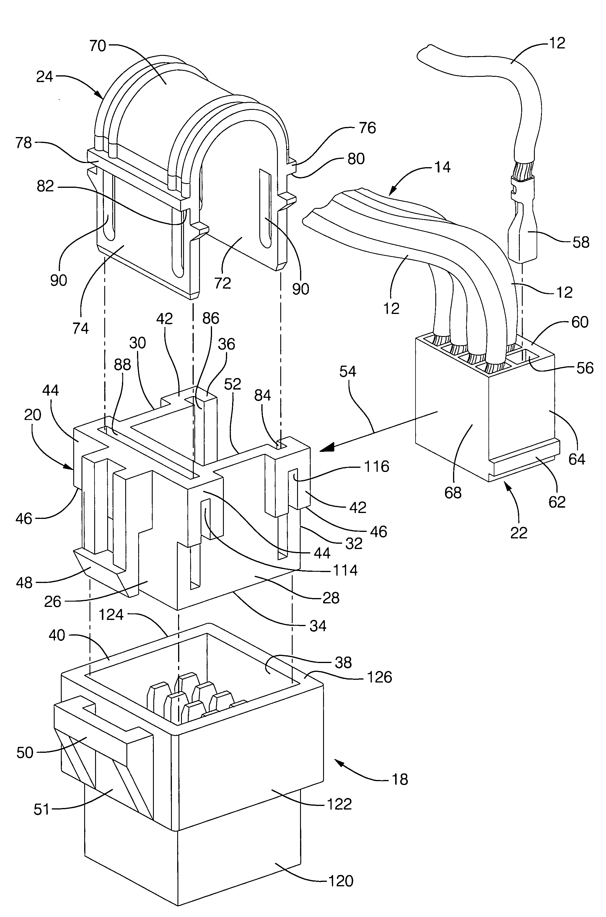
[0036]The present invention is intended for application in automotive vehicle systems and will be described in that context. It is to be understood, however, that the present invention could also be successfully applied in many other applications. Accordingly, the claims herein should not be deemed as limited to the specifics of the preferred embodiment of the invention as described hereunder. The preferred application of the present invention involves the interconnection of electrical or fiber optic conductors in an automotive system and represents an extremely robust, low cost, compact design, which can be easily configured to accommodate application specific packaging requirements. Furthermore, the connector configuration and arrangement enables use of simplified design and manufacturing processes, increasing turnover and lowering cost without adversely impacting quality and reliability.

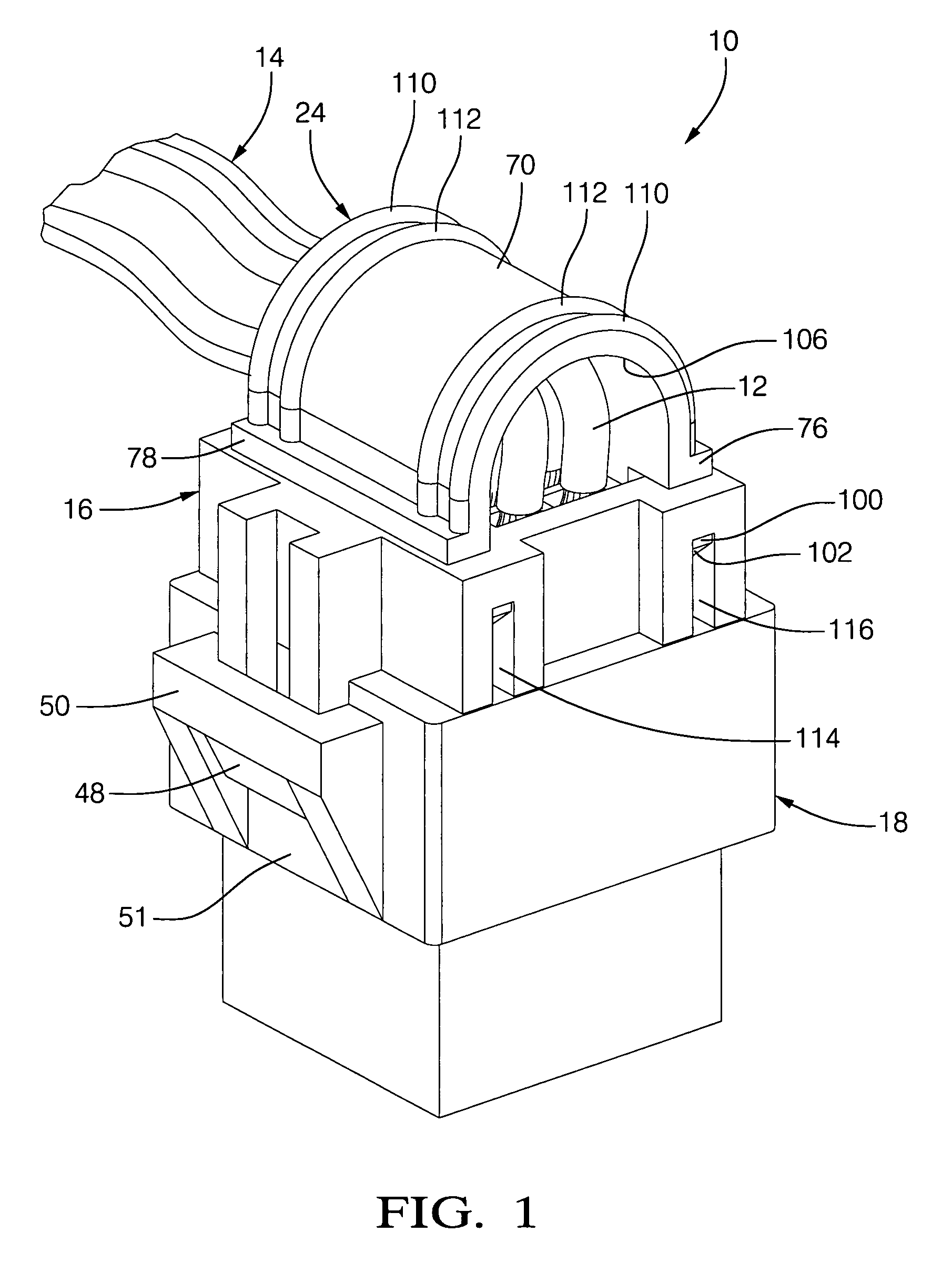
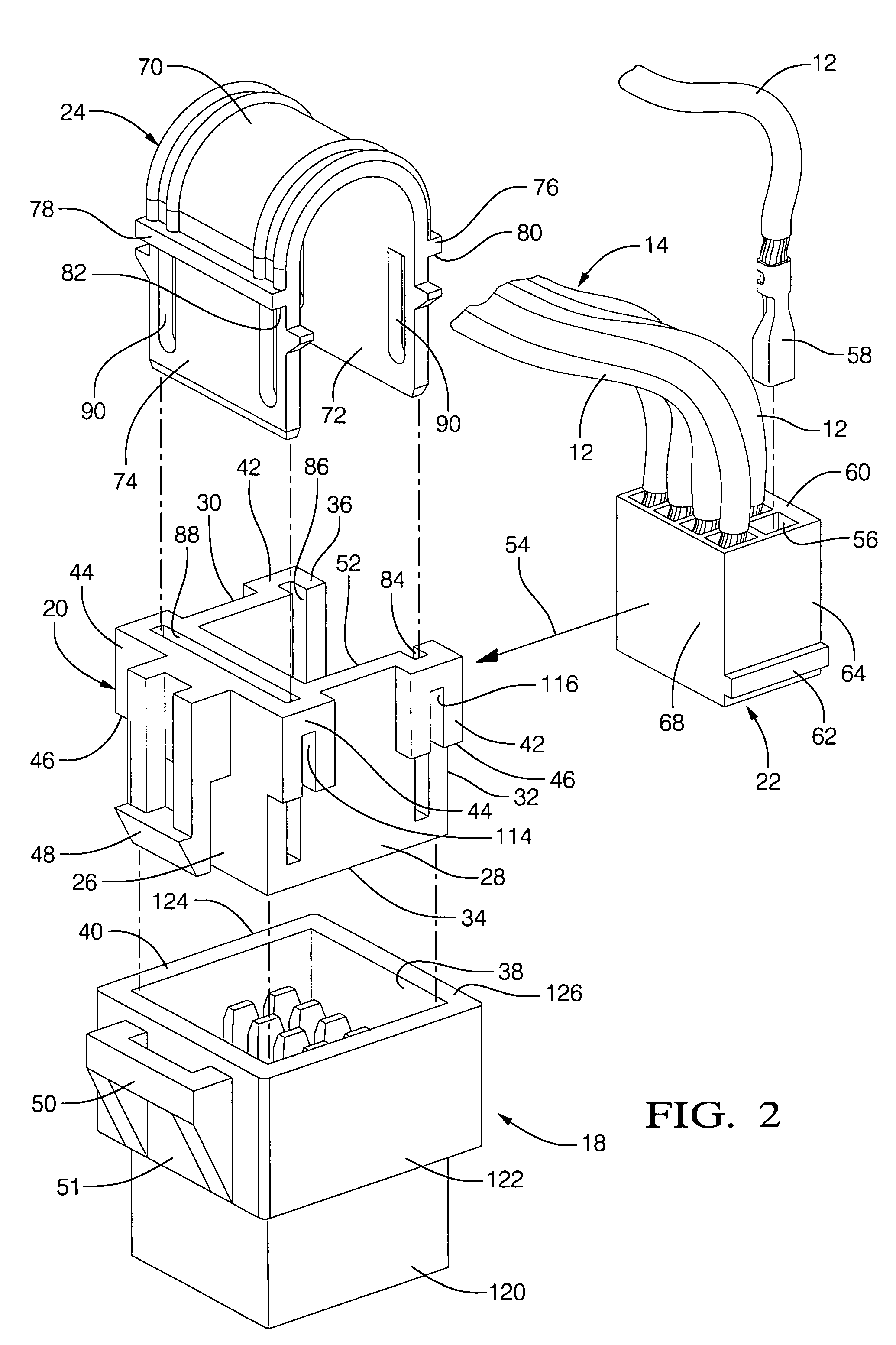
[0037]Referring to FIG. 1, an electrical connector assembly 10 is illustrated in-circuit with ...


PUM


Abstract

An electrical connector provides terminal position assurance and wire cover features in a single integrated structure. The connector has a body defining a cavity for receiving one or more terminal carriers having aligned terminal receiving passageways opening at an end surface. A slide member cooperates with the connector body to positionally fix the terminal carrier and to integrally support the wire cover to overlay the end surface to dress conductors emerging there from in a preferred orientation.

Description

RELATED PATENT APPLICATION[0001]The present application claims priority to provisional application U.S. Ser. No. 60 / 648,666, filed 31 Jan. 2005, entitled “Integrated TPA and Wire Cover.”TECHNICAL FIELD[0002]The present invention relates to electrical connectors, and more particularly to electrical connector assemblies employing connector body, terminal position and wire dress position assurance features.BACKGROUND OF THE INVENTION[0003]Electrical connectors for vehicles and the like are often comprised of separate housings that are engaged through pressure, or “snap-fit”, upon installation. Snap-fit connectors are desirable because of their ease of installation. However, in order to ensure proper installation, various complexities must be taken into account.[0004]For example, the housings must be securely fastened so that they do not come apart after installation. Additionally, they must be properly aligned so that an electrical connection is made upon installation.[0005]In order to...

Claims


Application Information

Patent Timeline
Patent Type & Authority Patents(United States)
IPC IPC(8): H01R13/502
CPCH01R13/447H01R13/506Y10S439/902
Inventor WASALASKI, PHILIP LEEMATOUSEK, DAVID G
Owner GM GLOBAL TECH OPERATIONS LLC
Why Eureka
Try Eureka