
Television receiver for digital signals with offset tuning provisions

Inactive Publication Date: 2007-07-03
INTERDIGITAL MADISON PATENT HLDG
View PDF16 Cites 21 Cited by
  • Summary
  • Abstract
  • Description
  • Claims
  • Application Information

AI Technical Summary

Benefits of technology

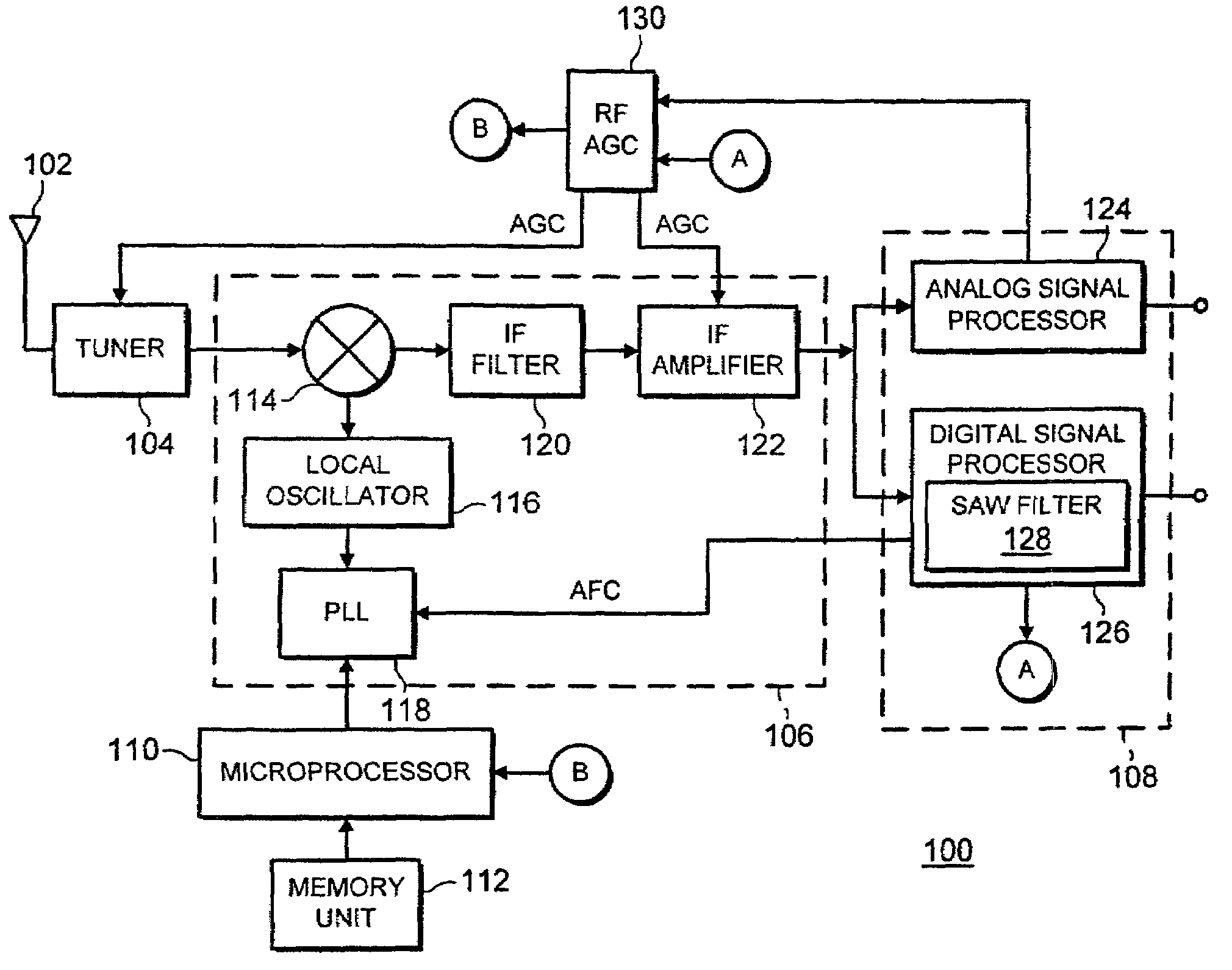
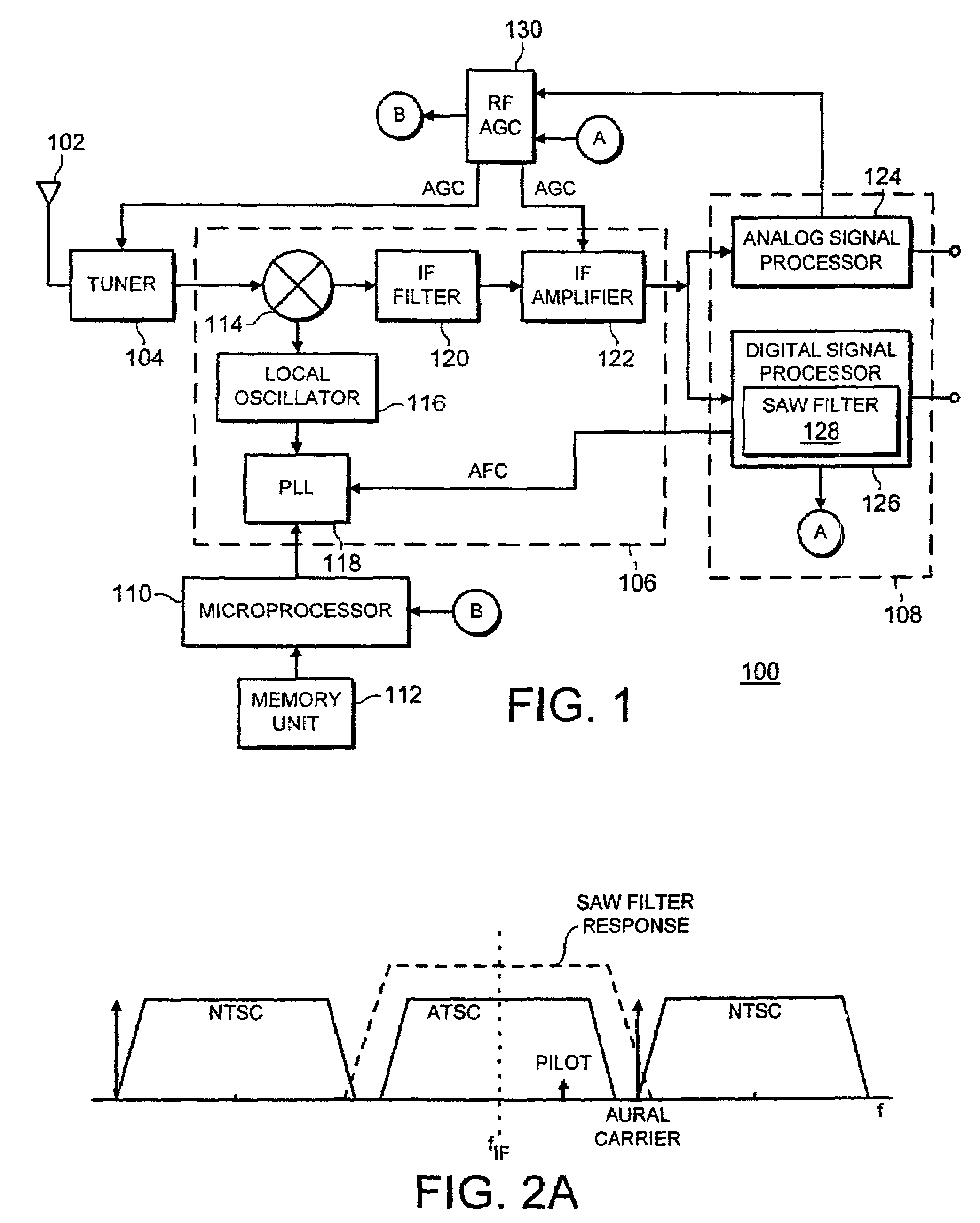
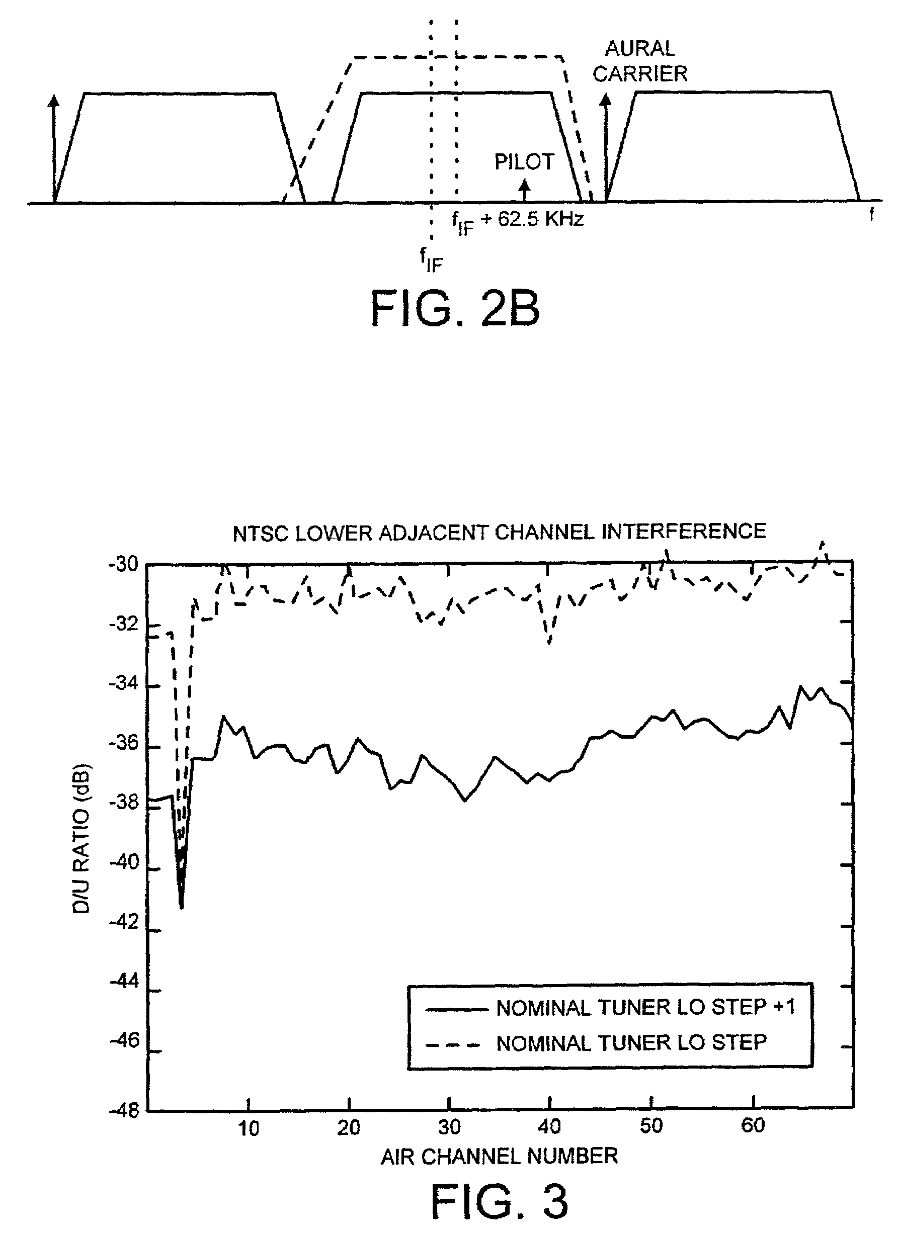
[0006]The invention overcomes the disadvantages associated with the prior art by providing a television receiver for reducing adjacent channel interference when receiving digital signals. Specifically, the invention tunes to a digital signal associated with a selected broadcast channel and downconverts the digital signal to an intermediate frequency (IF) signal. The center frequency of the IF signal is determined by a microprocessor, which searches a memory unit for information associated with a selected broadcast channel and determines the presence or absence of a lower adjacent NTSC analog channel. In the case a lower adjacent NTSC analog channel is present, the microprocessor causes the IF signal to be shifted by 62.5 kHz. The IF signal is thus pushed further towards the band edge of the surface acoustic wave filter present in the digital signal processor, resulting in further attenuation of the lower adjacent NTSC signal, particularly the aural carrier of the NTSC signal.
[0007]In an alternative embodiment of the invention, the microprocessor determines the input signal power of the tuned digital signal using data obtained from an automatic gain control (AGC) circuit. If the microprocessor determines the input signal power is larger than that of the adjacent channel, the microprocessor does not cause the frequency of the IF signal to be shifted from nominal.

Problems solved by technology

The IF signal is thus pushed further towards the band edge of the surface acoustic wave filter present in the digital signal processor, resulting in further attenuation of the lower adjacent NTSC signal, particularly the aural carrier of the NTSC signal.

Method used


Image

  • Television receiver for digital signals with offset tuning provisions
  • Television receiver for digital signals with offset tuning provisions
  • Television receiver for digital signals with offset tuning provisions

Examples


Embodiment Construction

[0014]FIG. 1 depicts a block diagram of a television receiver 100 in accordance with the present invention. The receiver 100 comprises a tuner 104 coupled to an RF source 102, a frequency conversion stage 106, a demodulation stage 108, a microprocessor 110 coupled to a memory unit 112, and an automatic gain control (AGC) circuit 130. The tuner 104 selects the radio frequency (RF) signal corresponding to a broadcast channel selected from a plurality of channel locations in a frequency band provided by the RF source 102. The RF signals associated with broadcast channels are analog and digital television signals. The analog television signal may comprise a conventional National Television Standard Committee (NTSC) modulated signal within the United States. The digital television signal may comprise a Vestigial Sideband (VSB) modulated signal in compliance with the Advanced Television Systems Committee (ATSC) standard A / 53, for example, a high definition television (HDTV) signal.

[0015]T...


PUM


Abstract

A television receiver for receiving digital and analog signals that reduces adjacent channel interference when receiving digital signals susceptible to interference caused by a lower adjacent NTSC signal. Upon receiving the digital signal, the receiver heterodynes the digital signal with a local oscillator (LO) signal to produce an intermediate frequency (IF) signal. A microprocessor searches a memory unit for stored information regarding the digital broadcast channel and determines the presence or absence of a lower adjacent NTSC channel. In the case a lower adjacent NTSC channel is present, the microprocessor shifts the frequency of the LO signal causing the IF signal to shift towards the lower band edge of a surface acoustic wave (SAW) filter present in a digital signal processor further attenuating the lower adjacent NTSC channel.

Description

[0001]This application claims the benefit under 35 U.S.C. § 365 of International Application PCT / US00 / 19103, filed Jul. 13, 2000, which was published in accordance with PCT Article 21 (2) on Jan. 25, 2001 in English; and which claims benefit of U.S. provisional application Ser. No. 60 / 144,415 filed Jul. 16, 1999.FIELD OF THE INVENTION[0002]The invention generally relates to a digital television receiver. More particularly, the invention relates to an apparatus for selectively offsetting the frequency of a desired signal to obtain greater attenuation of undesired signals.BACKGROUND OF THE DISCLOSURE[0003]A Digital Television Standard published by the Advanced Television Subcommittee (ATSC) specifies vestigial sideband (VSB) signals for transmitting digital television (DTV) signals, such as high definition television (HDTV) signals. The VSB signals are transmitted in 6-MHz handwidth television channels such as those currently used in conventional terrestrial broadcasting of National T...

Claims


Application Information

Patent Timeline
IPC IPC(8): H04N5/50
CPCH04N5/4401H04N5/46H04N21/4382H04N21/426H04N5/50
Inventor MAYER, MATTHEW THOMAS
Owner INTERDIGITAL MADISON PATENT HLDG
Learn More