
All-dielectric optically variable pigments

a dichroic pigment, optically variable technology, applied in the field of pigments, can solve the problems of maximum constructive light interference, change of color in the pigment, and constructive or destructive interference with the light reflected from the surface of the filter, and achieve the effect of unique color properties

Inactive Publication Date: 2007-07-03
VIAVI SOLUTIONS INC
View PDF38 Cites 28 Cited by
  • Summary
  • Abstract
  • Description
  • Claims
  • Application Information

AI Technical Summary

Benefits of technology

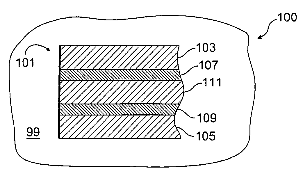
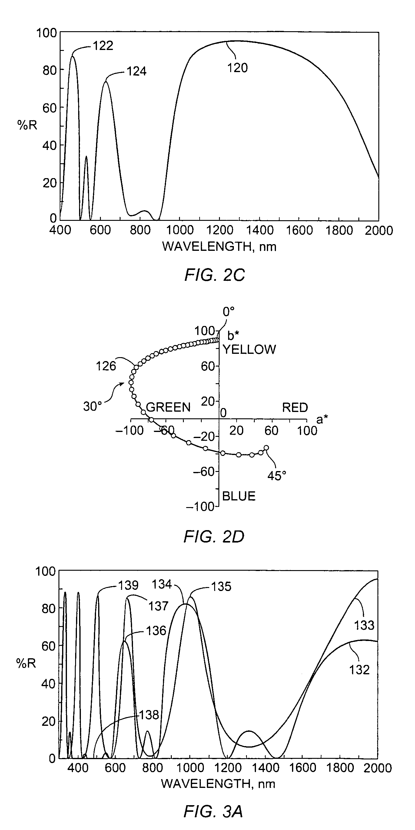
The invention is about creating special optical pigments that can produce unique colors in products like inks and paints. These pigments have layers that reflect light in a special way that creates a large color range and can change quickly between different colors. The pigments can also have a high reflectivity outside the range of human vision. These pigments can be used to create anti-counterfeit protection for valuable documents and articles. The patent describes a specific design for a dichroic pigment flake that has multiple layers with different refractive indices and thicknesses. The ratio of the layers and the wavelength of light can affect the color travel and reflectivity of the pigment. The pigment also has a reflectivity peak at a certain angle that is made up of two components with different reflectivities. The first reflectivity is less than the second reflectivity by at least 20%. This design allows for wide color travel and fast color travel, and can be used in low-index carriers or media like inks and paints.

Problems solved by technology

Changes of color in a pigment result from the interference of light beams reflected from thin layers of the stack.
A fraction of the reflected wave passes through the first layer where it may constructively or destructively interfere with the light reflected from the surface of the filter.
Maximum destructive reflective light interference occurs when the thickness of the layers are an odd number of quarter waves, whereas maximum constructive light interference occurs when the thickness of the layers are an even number of quarter waves.
Color-shifting optical interference devices are used to authenticate products and documents because copies of such articles made on conventional color printers do not achieve the color-shifting effect(s).
However, tuning the optical design of a flake or foil has several limitations in the resultant color performance.
Another limitation is that the peaks can be wide or narrow.

Method used


Image

  • All-dielectric optically variable pigments
  • All-dielectric optically variable pigments
  • All-dielectric optically variable pigments

Examples


Embodiment Construction

1. Introduction

[0031]The process control achievable with vacuum deposition techniques offers the possibility of predictable optically variable pigments and foils. It was discovered that computer modeling of reflectance versus wavelength and color travel, in air or preferably in a carrier with an index of refraction greater than air, such as paint, can be used to design pigment flakes having specific color characteristics without undue trial-and-error experimentation. Use of controllable vacuum thin-film deposition techniques can be used to consistently obtain pigment flakes with the selected optical properties. In particular, it was found that suppression of reflectivity peaks of non-desirable color could produce interference pigments with unique color-shifting characteristics. Such color performance is difficult to achieve by conventional optical design.

[0032]One aspect of vacuum deposition techniques is that the layer thickness is typically considered according to its optical thic...


PUM

PropertyMeasurementUnit
optical thicknessaaaaaaaaaa
reflectivityaaaaaaaaaa
wavelengthaaaaaaaaaa

Abstract

The light transmitted and reflected by all-dielectric optically variable pigments varies according to viewing angle. The color travel of an all-dielectric optically variable pigment depends on amplitude changes and wavelength shifts in reflectance peaks of the pigment. The width and center wavelength of reflectance peaks can be controlled by selecting the ratio of thicknesses between high-index and low-index layers in a thin film stack. Reflectance peaks can regenerate or become suppressed and shift with tilt angle, thus providing a wide variety of color trajectories.

Description

CROSS-REFERENCE TO RELATED APPLICATIONS[0001]The present application is a continuation-in-part of U.S. patent application Ser. No. 10 / 365,090 filed Feb. 11, 2003 now U.S. Pat. No. 6,815,065, which claimed priority from U.S. Patent Application No. 60 / 384,629 filed May 31, 2002, which are incorporated herein by reference for all purposes.STATEMENT REGARDING FEDERALLY SPONSORED RESEARCH OR DEVELOPMENT[0002]Not applicable.Reference to Microfiche Appendix[0003]Not applicable.Field of the Invention[0004]The present invention relates generally to pigments, and more particularly to optically variable dichroic pigment flakes used in paints, inks, and other products.BACKGROUND OF THE INVENTION[0005]Interference pigments and devices are well known. Usually, optically-variable thin-film pigment flakes are prepared either by chemical deposition of dielectric layers onto flaked substrates or by deposition of combinations of transparent dielectric layers, semi-opaque metal layers, and metal reflec...

Claims


Application Information

Patent Timeline
Patent Type & Authority Patents(United States)
IPC IPC(8): B32B5/16C09D4/00C09C1/00C09C1/62C09C3/06
CPCC09C1/0024C09C1/0051C09C1/0015C01P2006/62C01P2006/63C01P2006/64C01P2006/65Y10T428/2991C09C2200/308Y10S428/913C09C1/62
Inventor RAKSHA, VLADIMIR P.KOHLMANN, PAUL T.BRADLEY, RICHARD A.CARNIGLIA, CHARLES K.ARGOITIA, ALBERTOPHILLIPS, ROGER W.
Owner VIAVI SOLUTIONS INC
Learn More