
Pneumatic high speed motor with pressure activated speed governor

a high-speed motor and pneumatic technology, applied in the direction of wind motor control, motors, mechanical equipment, etc., can solve the problems of difficult to obtain an accurate enough control of the motor speed level, difficult to get the mechanical speed governor to operate properly, etc., to achieve high-speed operation and improve the accuracy of speed control

Active Publication Date: 2007-07-03
ATLAS COPCO TOOLS AB
View PDF5 Cites 1 Cited by
  • Summary
  • Abstract
  • Description
  • Claims
  • Application Information

AI Technical Summary

Benefits of technology

[0005]The main object of the invention is to provide a pneumatic high speed motor with a pressure controlled speed governor coping with high speed operation and giving an improved speed control accuracy.
[0006]Another object of the invention is to provide a pneumatic high speed motor with an improved speed governor enabling a simple and compact motor design.

Problems solved by technology

A problem concerned with speed control of high speed motors, for instance air turbines, is that mechanical speed governors are difficult to get to operate properly at high speed levels due to high dynamic forces, balancing problems etc.
This previously known device is less advantageous in that it is difficult to obtain an accurate enough control of the motor speed level.

Method used


Image

  • Pneumatic high speed motor with pressure activated speed governor
  • Pneumatic high speed motor with pressure activated speed governor

Examples


Embodiment Construction

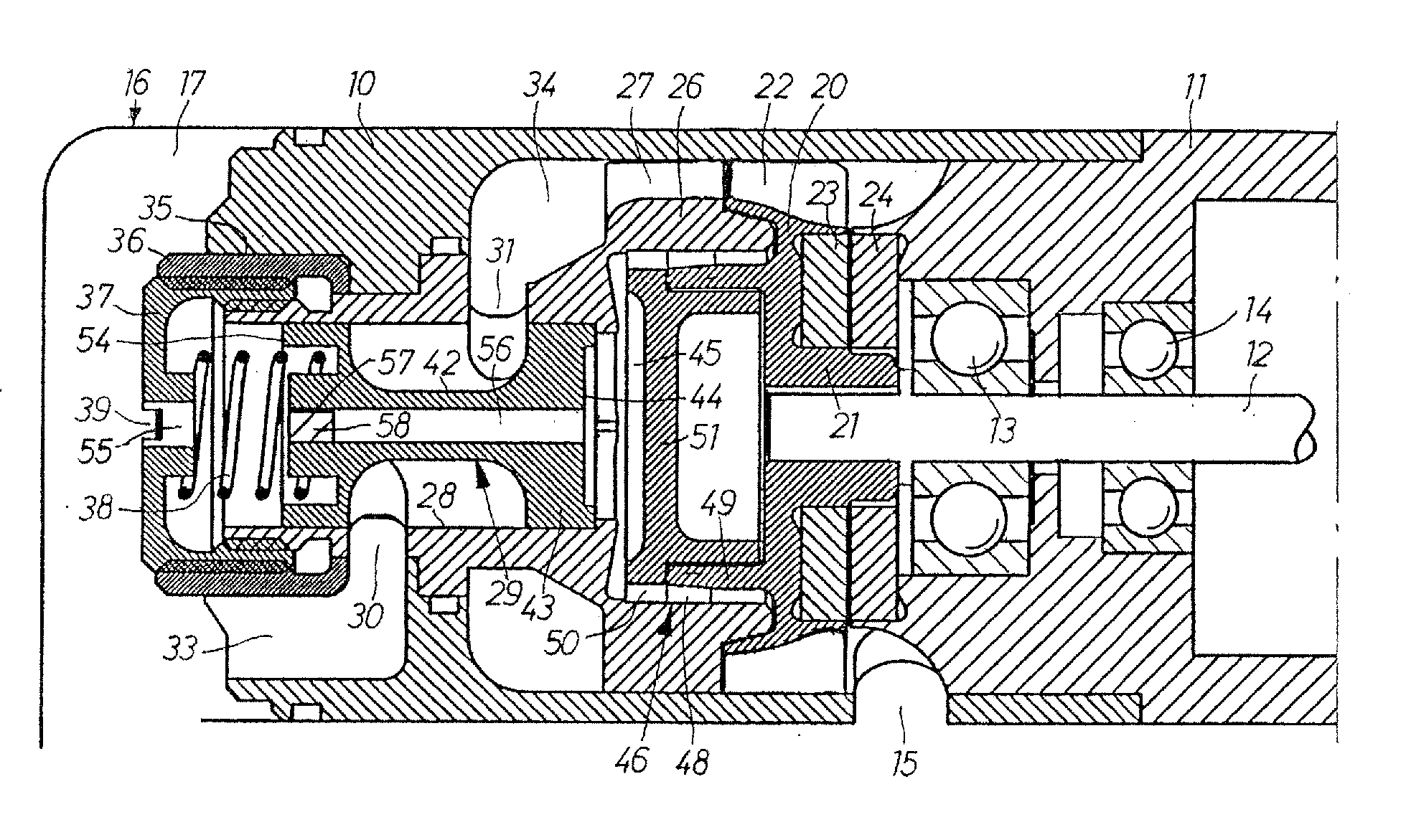
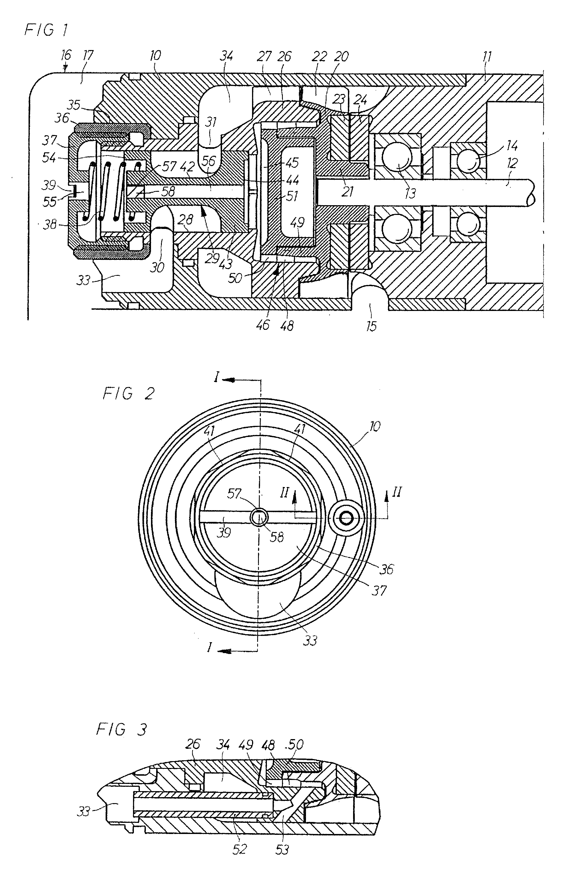
[0013]The turbine motor illustrated in the drawing figures comprises a stator housing 10 which at its one end is rigidly secured to a transmission casing 11 supporting a drive spindle 12 via two spindle bearings 13,14. At its opposite end the stator housing 10 is connected to a support and pressure air inlet housing 16 including a pressure air inlet chamber 17 communicating with a pressure air source via a suitable conduit connection (not shown). Exhaust air from the motor is vented through a lateral outlet opening 15.

[0014]A turbine rotor 20 is journalled in the stator housing 10 via the bearings 13,14 and has a concentric socket portion 21 for connection to the drive spindle 12. The rotor 20 carries a circumferential row of drive blades 22 to be acted upon by pressure air as described below.

[0015]For dealing with the axial load acting on the rotor 20 during operation, there is provided a magnetic type thrust bearing which provides not only an extremely low frictional resistance be...


PUM


Abstract

A pneumatic high speed motor includes a stator housing, a rotor journalled in the stator housing, and a pressure air inlet passage. A speed governor for the motor includes a valve element that is shiftable between an open position and a closed position for controlling pressure air flow through the pressure air inlet passage, and a spring which continuously biases the valve element toward open position. An air compressor is driven by the rotor to deliver an output pressure, which is responsive to a speed of the rotor, to an activating surface of the valve element. The activating surface of the valve element is acted upon by the output pressure of the air compressor to shift the valve element toward the closed position against the bias force of the spring at rotor speed levels exceeding a desired operating speed level.

Description

[0001]This application is a U.S. National Phase Application under 35 USC 371 of International Application PCT / SE2003 / 001575 filed Oct. 10, 2003.FIELD OF THE INVENTION[0002]The invention relates to a pneumatic high speed motor provided with a pressure air inlet flow controlling speed governor valve as stated in the claims.BACKGROUND OF THE INVENTION[0003]A problem concerned with speed control of high speed motors, for instance air turbines, is that mechanical speed governors are difficult to get to operate properly at high speed levels due to high dynamic forces, balancing problems etc.[0004]One way of solving this problem is described in U.S. Pat. No. 5,314,299 wherein the rotation speed of a power tool air turbine is governed by a pressure air inlet flow controlling valve which is activated by the air pressure in a pressure sensing opening in the turbine stator. A co-operation between the pressure sensing opening and an oppositely located idle running nozzle in the turbine stator r...

Claims


Application Information

Patent Timeline
IPC IPC(8): F03D7/00F01D15/06F01D17/06
CPCF01D15/06F01D17/06Y10S415/904
Inventor ELSMARK, KARL JOHAN LARS
Owner ATLAS COPCO TOOLS AB
Learn More