
Particle use for image display media, image display panel using the particles, and image display device

a technology of image display media and particle, applied in the direction of static indicating devices, instruments, optics, etc., can solve the problems of lack of imaging repetition stability, slow response rate, and difficulty in maintaining a stable dispersion sta

Inactive Publication Date: 2007-06-26
BRIDGESTONE CORP
View PDF4 Cites 653 Cited by
  • Summary
  • Abstract
  • Description
  • Claims
  • Application Information

AI Technical Summary

Benefits of technology

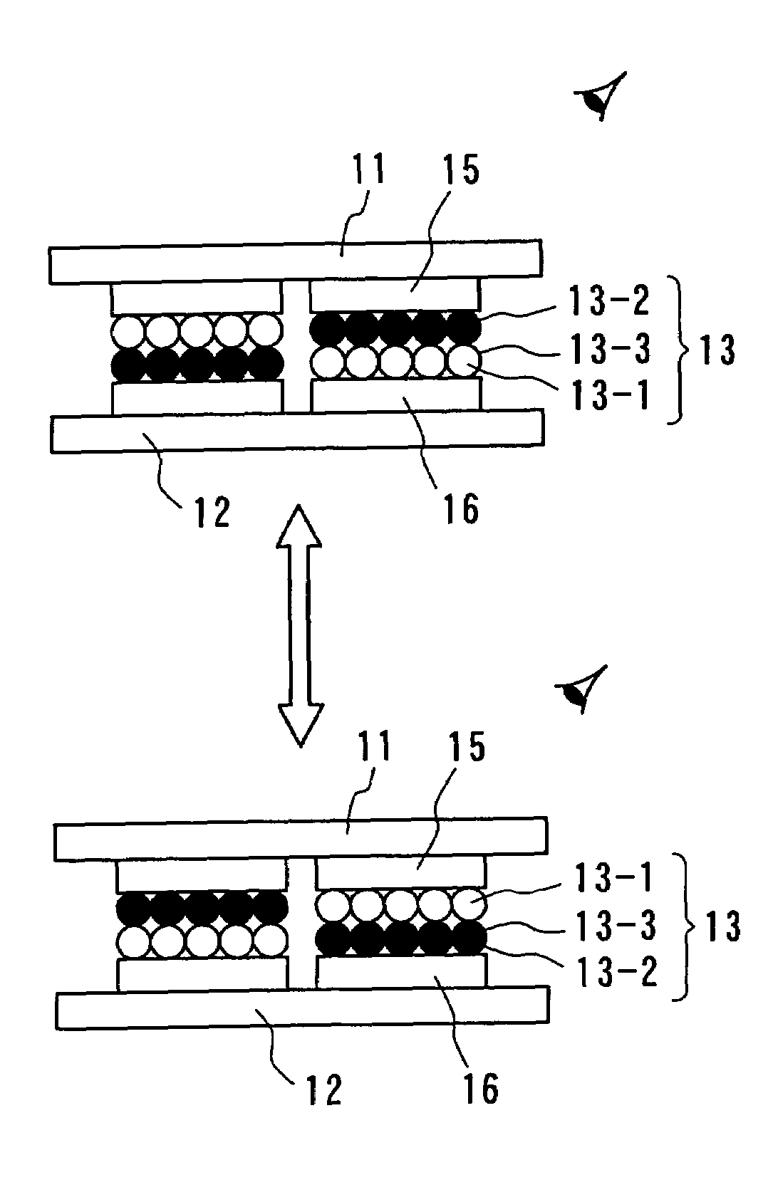
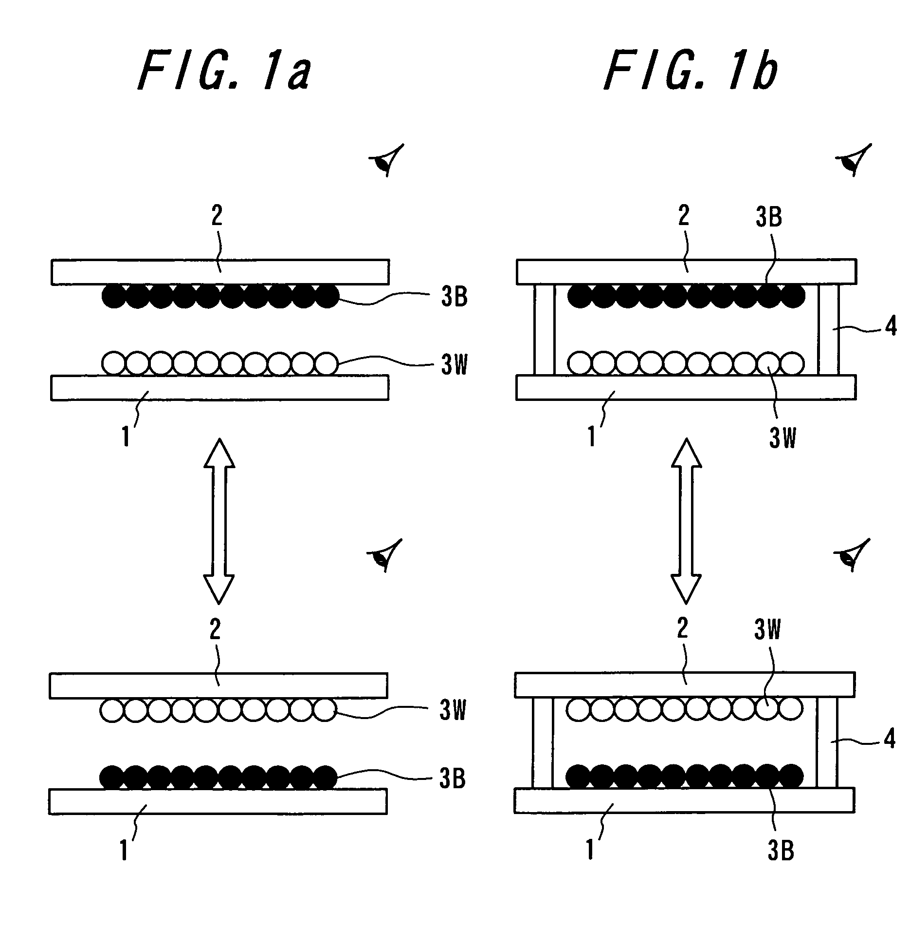
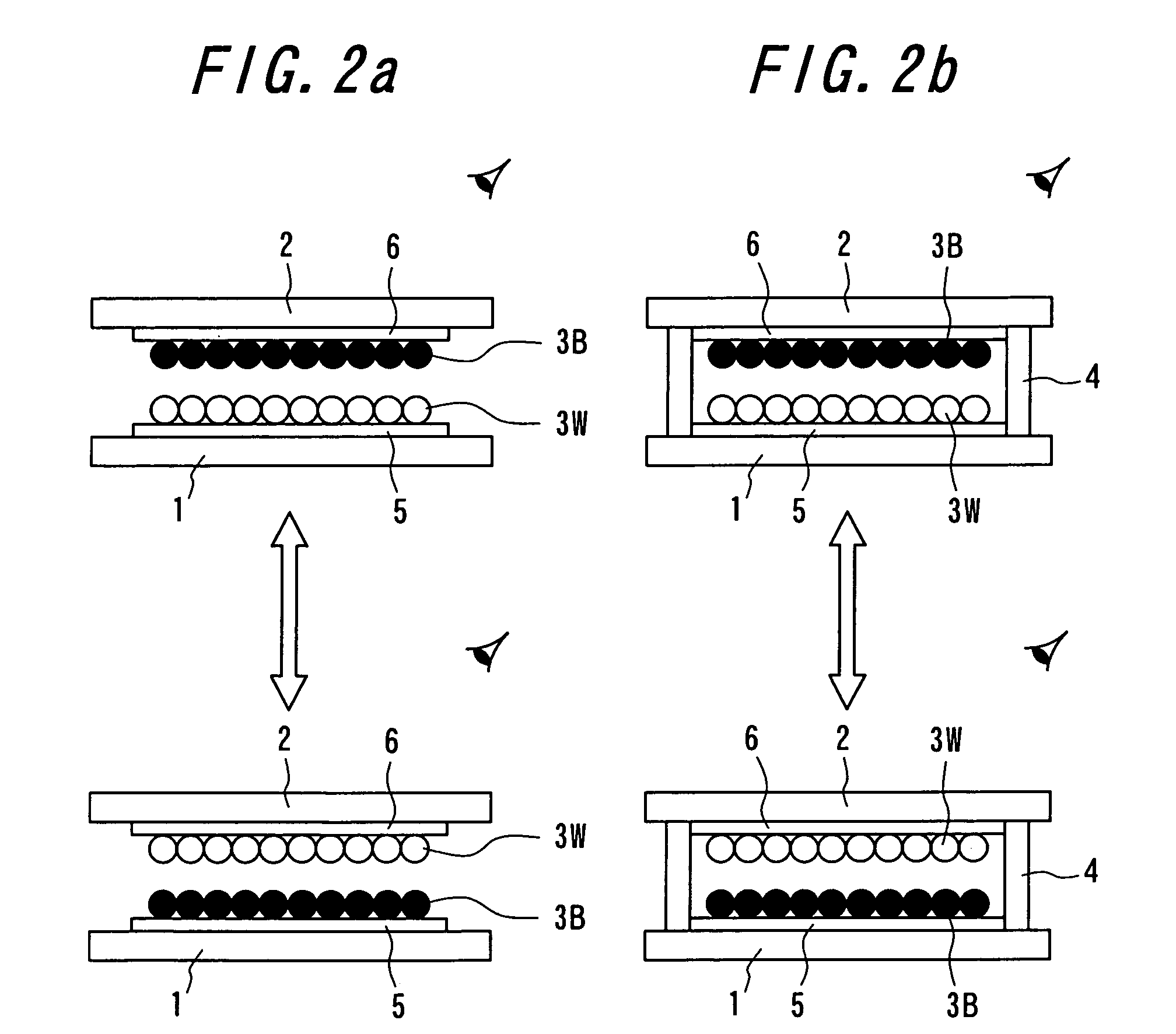
The invention provides white particles used as image display media with improved luminance factors and durability during repetitive use. The white particles have a center portion with a high reflectance rate and an outer portion with a lower reflectance rate, which reduces the amount of light transmitted through the thin image display media layer. The particles are made by sealing between two substrates and applying an electrostatic field to display an image. The image display panel has at least two groups of image display media with different colors and different charge characteristics, which prevents agglutination and adherence of particles. The particles are made of a resin layer with high reflectance materials mixed with low reflectance materials. The particles can be further improved by adding a third layer with a high reflectance material to prevent agglutination. The image display device using these particles has excellent durability and low cost.

Problems solved by technology

However, in the electrophoresis method, there is a problem that a response rate is slow by the reason of viscosity resistance because the particles migrate among the electrophoresis solution.
Further, there is a problem of lacking imaging repetition stability, because particles with high specific gravity of titanium oxide is scattered within solution of low specific gravity, it is easy to subside, difficult to maintain a stability of dispersion state.
Even in the case of microencapsulating, cell size is diminished to a microcapsule level in order to make it hard to appear, however, an essential problem was not overcome at all.
[The Imaging Society of Japan “Japan Hardcopy '99” (Jul. 21–23, 1999) Transaction Pages 249–252] However, the structure becomes complicated because the charge transport layer and further a charge generation layer are to be arranged.
In addition, it is difficult to constantly dissipate charges from the electro-conductive particles, and thus there is a drawback on the lack of stability.
An opacifying rate becomes insufficient, and thus there is a limit for an achievable luminance factor.
Therefore, there occurs a problem such that an image contrast is deteriorated, and thus a durability after the repetition use is insufficient.
In this case, the number of the particles adhered to a display electrode surface becomes small, and thus there occurs a problem such that a display performance is extremely deteriorated.
However, it is difficult to crush the agglutinated cluster in the same manner if the agglutinated cluster is formed by the particles having the same charge characteristics.
In this case, it is not possible to crush the agglutinated cluster by en external electronic stress, and thus a solving method is not certain.
However, in the crushed particles, there are problems: such that a desired color is not obtained since a particle shape is varied and there is a limit for filling amounts of the pigment and dye; and such that the particles have a damage such that a crack generation and so on when crushed.
Moreover, in the polymerized particles, there is a problem such that filling amounts of the pigment and dye become further smaller and thus a desired color is not obtained.
Further, in the composite particles, there are problems: such that a coloring is insufficient since the pigment and dye are not existent in the mother particles; such that the pigment and dye are easily picked away from the surface; and such that manufacturing processes are made larger.
Therefore, there occurs a problem such that an image contrast is deteriorated, and thus a durability after the repetition use is insufficient.
However, in the mixing / crushing method, if titanium oxide is added more and more to a high extent, a scattering becomes insufficient and thus there is a problem such that a white refraction index decreases.
Then, if titanium oxide is added over 300 parts by weight, it is difficult to perform a mixing process and the white refraction index also decreases.
Particularly, in the case of using titanium oxide, there is a problem such that it is difficult to fill over 300 parts by weight of titanium oxide with respect to 100 parts by weight of the base resin.
Therefore, there is a problem such that the particles are melted and thus adhered / agglutinated to the image display panel during the use of the image display panel under a high temperature or during the works under a high temperature such as a substrate stacking process of the image display panel.
In the dry-type image display panel mentioned above, an image contrast is not still sufficient, and there occurs a phenomenon such that the sealed particles do not move after a repetition use because of particle adhesions with each other.
Therefore, there occurs a problem such that an image contrast is deteriorated, and thus a durability after the repetition use is insufficient.
Heretofore, it is not possible to control charge characteristics (positive charge performance and negative charge performance) of a particle material constituting image display media using the image display device having the dry-type image display panel, and the charge characteristics are a value inherent from a resin material constituting the image display media itself.

Method used


Image

  • Particle use for image display media, image display panel using the particles, and image display device
  • Particle use for image display media, image display panel using the particles, and image display device
  • Particle use for image display media, image display panel using the particles, and image display device

Examples


example 1

Particles

[0258]An aluminum ball having an average particle diameter of 7.0 μm was used for the center portion constituting a core. A total reflection rate on the surface of the aluminum ball constituting the center portion to be used (corresponding to a boundary between the center portion and the outer portion) was 85%. The known white material was coated to the aluminum ball constituting the center portion by means of Agglomaster (HOSOKAWA MICRON CORPORATION) so as to form the outer layer portion, and the white particle according to the invention was obtained.

[0259]The white material was produced in such a manner that acrylic urethane resin: EAU53B (Asia Industry Co., Ltd.) / IPDI cross-linking agent: Excel-Hardener HX (Asia Industry Co., Ltd.), titanium oxide 10 phr, charge control agent: BontronE89 (Orient Chemical Industries Ltd.) 2 phr were added, mixed, ground and classified by a jet-mill.

[0260]The thus produced white particle had an average particle diameter of 9.0 μm and a sur...

example 2

Particles

[0261]A particle, in which aluminum was deposited by 500 nm on a PMMA ball having an average particle diameter of 5.0 μm, was used as the center portion constituting the core. A total reflection rate on the surface of the aluminum deposited film constituting the center portion to be used (corresponding to a boundary between the center portion and the outer portion) was 82%. The known white material was coated to this center portion by means of Agglomaster (HOSOKAWA MICRON CORPORATION) so as to form the outer layer portion, as is the same as the example 1, and the white particle according to the invention was obtained.

[0262]The thus produced white particle had an average particle diameter of 8.0 μm and a surface charge density of −50 μC / m2. Moreover, luminance factors of the base white particle and the white particle according to the invention were measured, and as a result, the luminance factor of the white particle according to the invention was improved by 4% with respect...

example 3

Particles

[0263]A particle, in which titanium oxide having a film thickness of 80 nm and silicone oxide having a film thickness of 100 nm were alternately deposited on a PC ball having an average particle diameter of 5.0 μm, was used as the center portion constituting the core. A total reflection rate on the surface of the deposited film constituting the center portion to be used (corresponding to a boundary between the center portion and the outer portion) was 91%. The known white material was coated to this center portion by means of Agglomaster (HOSOKAWA MICRON CORPORATION) so as to form the outer layer portion, as is the same as the example 1, and the white particle according to the invention was obtained.

[0264]The thus produced white particle had an average particle diameter of 7.0 μm and a surface charge density of −60 μC / m2. Moreover, luminance factors of the base white particle and the white particle according to the invention were measured, and as a result, the luminance fac...


PUM

PropertyMeasurementUnit
particle diameteraaaaaaaaaa
reflectanceaaaaaaaaaa

Abstract

An image display device, in which image display media are sealed between opposed substrates, at least one of two substrates being transparent, and in which the image display media, to which an electrostatic field is applied, are made to move so as to display an image. A construction of particles used as the image display media is improved (the first, second, fourth, fifth, sixth, eighth and ninth aspects of the invention), and a material of the particles used as the image display media is improved (the third, seventh and tenth aspects of the invention). Whiteness of the particles and a liquid powder using the particles is improved, particle agglutination is prevented, and the charge property is controlled. Moreover, durability is improved such that a contrast of the image display during a repetition display is not decreased. As a result, an excellent image display can be achieved.

Description

TECHNICAL FIELD[0001]The present invention relates to particles, liquid powder used for a reversible image display device enables to repeatedly display images accompanied by flight and movement of particles or liquid powder utilizing Coulomb's force, an image display panel using the particles or the liquid powder and an image display device.BACKGROUND ART[0002]As an image display device substitutable for liquid crystal display (LCD), image display devices with the use of technology such as an electrophoresis method, an electro-chromic method, a thermal method, dichroic-particles-rotary method are proposed. As for these image display device, it is conceivable as inexpensive visual display device of the next generation from a merit having wide field of vision close to normal printed matter, having smaller consumption with LCD, spreading out to a display for portable device, and an electronic paper is expected.[0003]Recently, electrophoresis method is proposed that microencapsulate dis...

Claims


Application Information

Patent Timeline
Patent Type & Authority Patents(United States)
IPC IPC(8): G02B26/00G02F1/167G02F1/1671
CPCG02F1/167G02F1/1671G02F2001/1678
Inventor KAGA, NORIHIKOYAKUSHIJI, GAKUTAZAWA, HAREMASUTANI, MAKIKOBAYASHI, TAICHIARAI, TOSHIAKIMURATA, KAZUYASAKURAI, RYOKOBAYASHI, YONEJITAMURA, HAJIMEANZAI, HIROYUKIYAMAZAKI, HIROTAKANISHIMURO, YOICHIMACHIDA, KUNIO
Owner BRIDGESTONE CORP
Learn More