Hydrocephalus shunt system with endoscopic placement features

a technology of endoscopic placement and shunt system, which is applied in the field of medical devices, can solve the problems of subdural hematoma, brain tissue compression, and impaired blood flow, and achieve the effect of fast and easy assembly

Active Publication Date: 2007-06-26
INTEGRA LIFESCI SWITZERLAND SARL
View PDF27 Cites 47 Cited by
  • Summary
  • Abstract
  • Description
  • Claims
  • Application Information

AI Technical Summary

Benefits of technology

[0008]The present invention provides a shunt system for controlling the flow of fluid from one region of a patient to a different region of the patient's body. The shunt system includes endoscopic placement features so that the system can be placed endoscopically for implantation in a minimally invasive surgery. Also provided is a single, fluid flow control device having flow control characteristics previously obtainable only by connecting in series two or more shunt system components. In addition, the shunt system can be assembled quickly and easily, without the need for suturing. The present assembly process minimizes the possibility of any unintended fluid leakage from the device, and preferably requires no adhesive to secure any of the components forming the shunt system to one another.
[0010]In one aspect of the present invention, the connector includes a flange while the inflow catheter includes an attachment end that fits over the flange. The inner diameter of the attachment end is configured to be slightly smaller than the largest outer diameter of the flange, thereby enabling an interference fit to be formed when the attachment end is urged over the connector and flange. Included with the inflow catheter is a selectively engageable locking mechanism that is adapted to secure the attachment end of the inflow catheter to the connector. The locking mechanism comprises a retaining ring for maintaining the attachment end of the inflow catheter onto the connector. Once fully assembled, the inflow catheter extends at approximately 90° with respect to the outflow catheter. The ventricular catheter can have either an open or a closed second end configured for fluid uptake. If the fluid uptake end is closed, a pre-slit can be provided so as to allow an endoscope to pass through the second end. A series of apertures can be provided near the second end to facilitate the entry of fluid into the catheter.
[0011]In one exemplary embodiment, the retaining ring can be provided on the inflow catheter, and can be configured to slide along the inflow catheter and towards the attachment end of the inflow catheter when the attachment end is fitted onto the connector. When advanced over the flange, the retaining ring compresses the attachment end around the flange and thereby secures the inflow catheter onto the connector. The inflow catheter can also include indicia on the outer surface of the catheter to designate corresponding lengths. The marks can aid the surgeon in pre-sizing the ventricular catheter to individual patients once the specific catheter size desired has been determined by either CT scan or other known imaging techniques. This way, the surgeon can adjust the length, i.e., by cutting the catheter to the required size, intraoperatively. After the inflow catheter has been cut to the desired size, the retaining ring can be advanced near the attachment end prior to assembly.
[0013]In other aspects of the present invention, the reservoir can be a domed reservoir while the housing can include a domed cap for accommodating the domed reservoir. Within the reservoir, a check valve mechanism is provided in the base portion to prevent occlusion of the shunt device during pumping of the valve mechanism. The check valve mechanism can comprise a free floating ball. The reservoir also includes surface features that provide the valve mechanism with anti-siphon properties. For example, the base portion can be provided with a central flow channel that connects to peripheral flow channels. Helically arranged ridges can be included within the peripheral flow channels to provide a tortuous fluid flow pathway with greater resistance to prevent siphoning. Also, the domed cap can include an endoscope port comprising a pre-formed slit that connects to the top portion of the reservoir. The endoscope port can be formed from a resealable silicone to allow an endoscope to pass through the housing and down into the reservoir base portion itself. The endoscope port can also be radiopaque to allow easy visualization and identification. The free-floating ball of the check valve mechanism can be pushed aside or manipulated aside with the endoscope.

Problems solved by technology

If left untreated, the increasing volume of fluid elevates the patient's intracranial pressure and can lead to serious medical conditions such as subdural hematoma, compression of the brain tissue, and impaired blood flow.
Because of the limited space available for the surgeon to perform the suturing after the proximal catheter is advanced into the ventricles, the assembly procedure after endoscopic implantation of the shunt system components can be extremely difficult.
Also, shunts having domed reservoirs are not easily occluded for flushing distally.
Given the amount of time necessary to suture the surgical tubing that connects the ventricular catheter to the shunt valve, the length of the surgical procedure can prove to be less than desirable.
An added setback to using these conventional shunt systems is the compatibility problems that arise when the various components are produced by different manufacturers.
Furthermore, currently available shunt systems can be prone to shunt separation and / or leakage at the sites where the separate components are connected to one another via the surgical tubing.

Method used


Image

  • Hydrocephalus shunt system with endoscopic placement features
  • Hydrocephalus shunt system with endoscopic placement features
  • Hydrocephalus shunt system with endoscopic placement features

Examples


Embodiment Construction

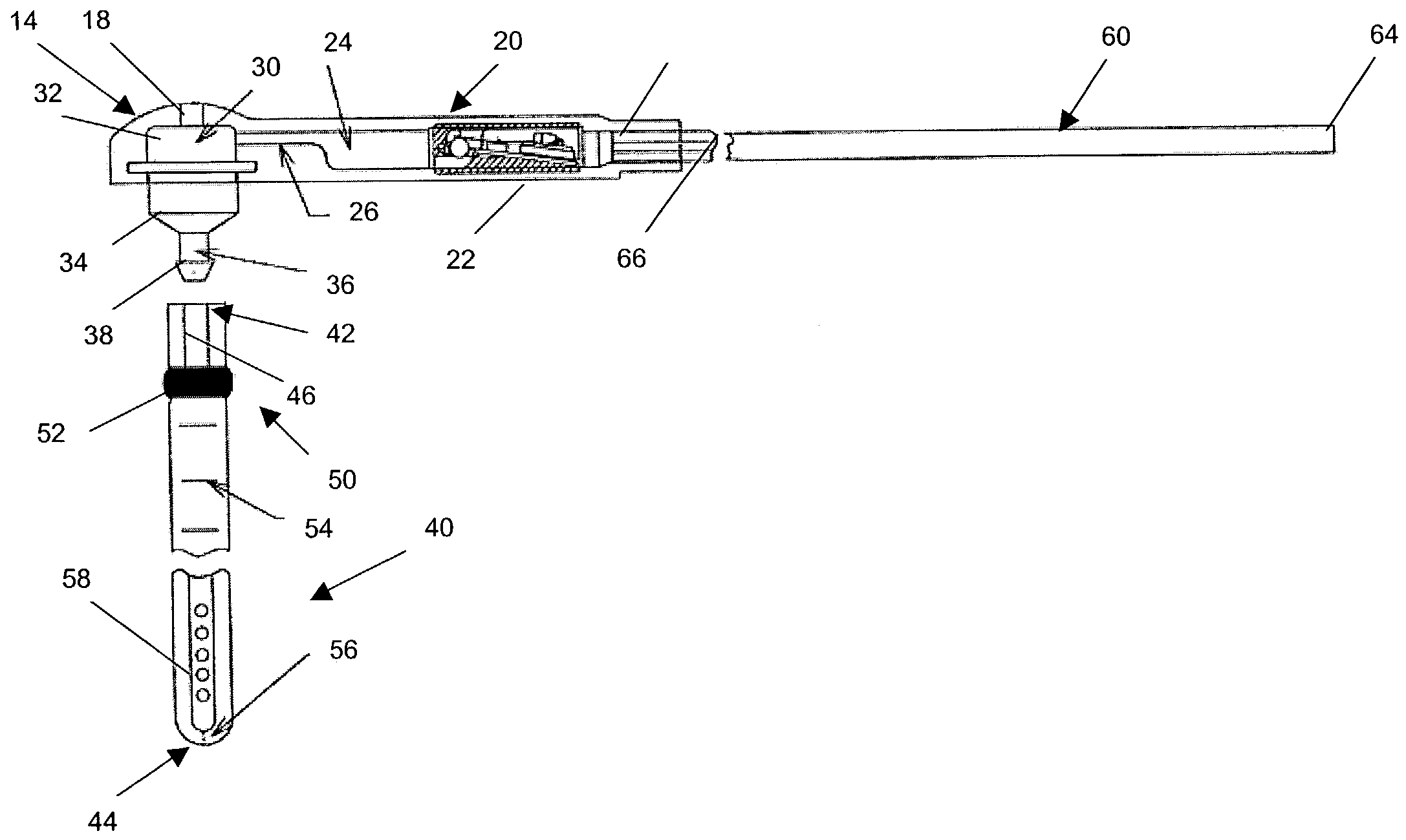
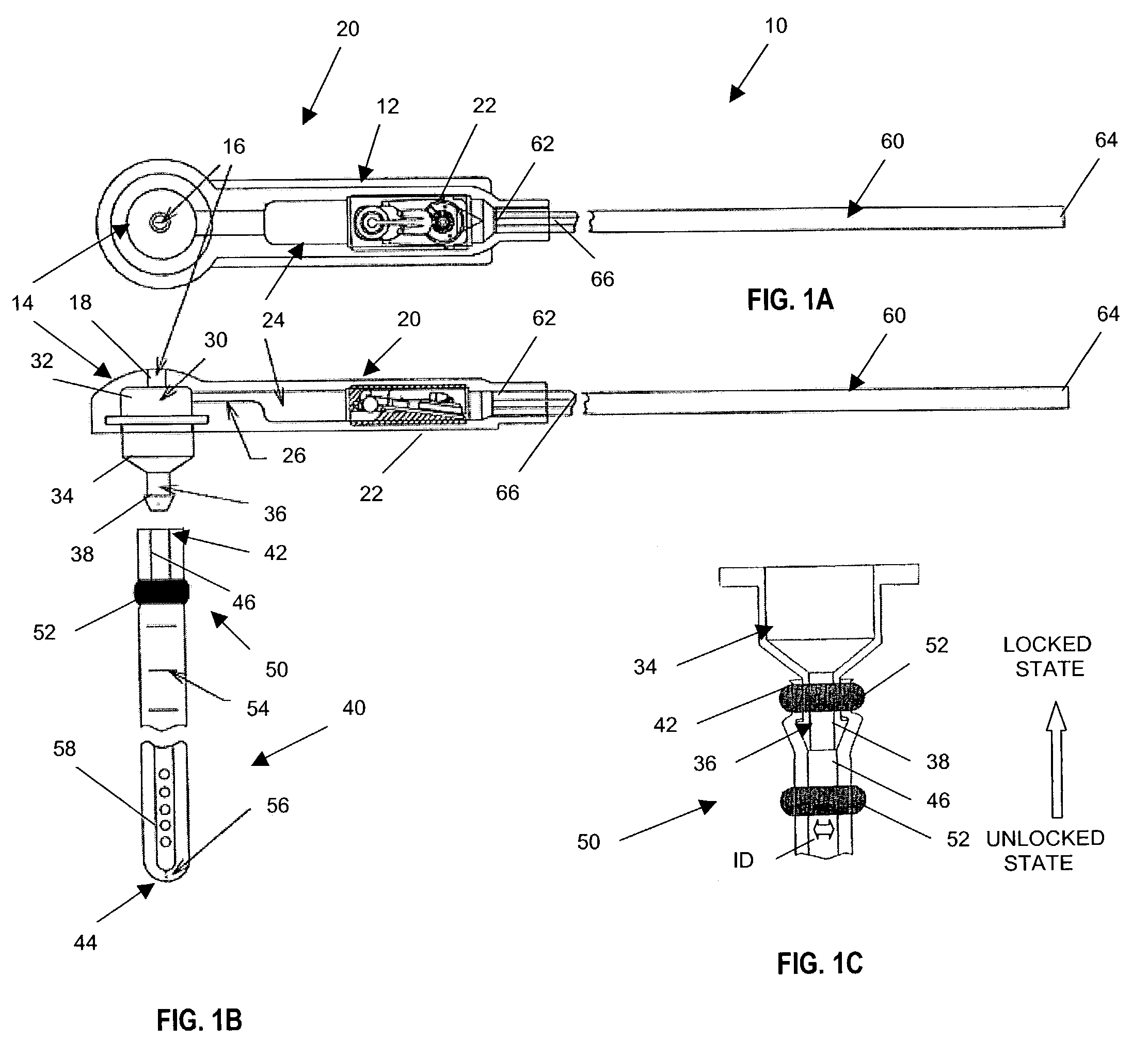
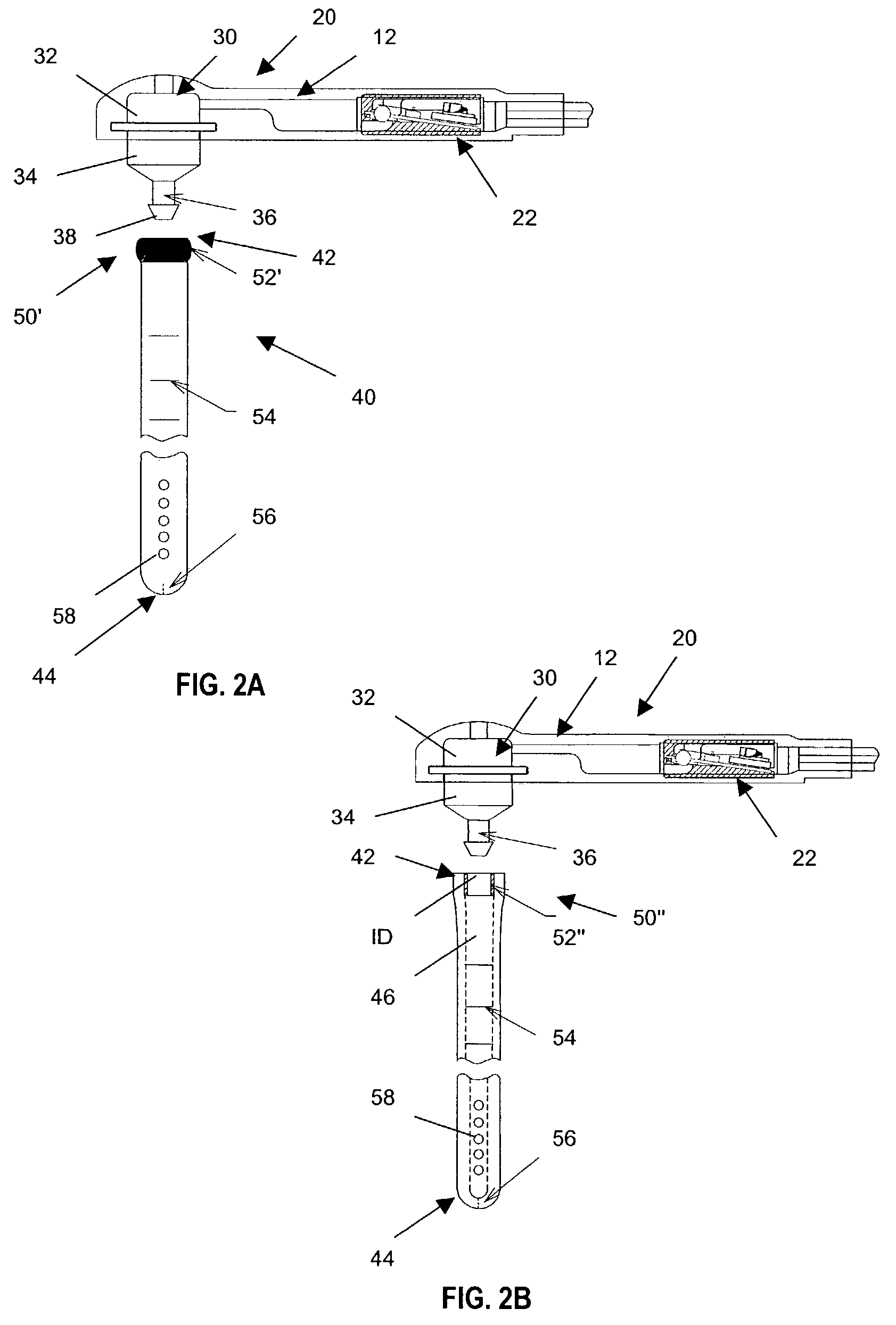
[0032]The present invention provides a shunt system having endoscopic placement features which allow the system to be surgically implanted and easily assembled using minimally invasive techniques. Turning now to the drawings and particularly to FIGS. 1A and 1B, a shunt system 10 in accordance with the present invention is shown. In an exemplary embodiment of the present invention, the shunt system 10 comprises a shunt device 20 contained within a housing 12. The shunt device 20 includes a valve mechanism 22 for regulating fluid flow into and out of the shunt device 20. The valve mechanism 22 can comprise any typical valve mechanism, such as the ball-in-cone valve illustrated and as described in U.S. Pat. Nos. 3,886,948, 4,332,255, 4,387,715, 4,551,128, 4,595,390, 4,615,691, 4,772,257, and 5,928,182, all of which are hereby incorporated by reference. Of course, it is understood that the valve mechanism 22 can also comprise other suitable valves including programmable valves for contr...


PUM


Abstract

A shunt system for controlling the flow of fluid from one region of a patient to a different region of the patient's body. The shunt system includes endoscopic placement features so that the system can be placed endoscopically in a minimally invasive surgery. Also provided is a single fluid flow control device having flow control characteristics previously obtainable only by connecting in series two or more shunt system components. In addition, the shunt system includes a selectively engageable locking mechanism that allows the system to be assembled quickly and easily, without the need for sutures or adhesives. The present assembly process minimizes the possibility of any unintended fluid leakage from the device.

Description

CROSS-REFERENCE TO RELATED APPLICATIONS[0001]Not applicable.STATEMENT REGARDING FEDERALLY SPONSORED RESEARCH[0002]Not Applicable.FIELD OF THE INVENTION[0003]The present invention relates to medical devices for directing bodily fluids from one region of a patient to another region. More specifically, this invention relates to a shunt system having endoscopic placement features that allow its minimally invasive placement within a patient, and apparatus to facilitate such endoscopic placement.BACKGROUND OF THE INVENTION[0004]Hydrocephalus is a condition afflicting patients who are unable to regulate cerebrospinal fluid flow through their body's own natural pathways. Produced by the ventricular system, cerebrospinal fluid is normally absorbed by the body's venous system. In a patient suffering from hydrocephalus, the cerebrospinal fluid is not absorbed in this manner, but instead accumulates in the ventricles of the patient's brain. If left untreated, the increasing volume of fluid elev...

Claims


Application Information

Patent Timeline
IPC IPC(8): A61M5/00A61M25/00A61B1/00A61M1/00A61M27/00
CPCA61M27/006
Inventor KRAUS, ROBERT G.
Owner INTEGRA LIFESCI SWITZERLAND SARL
Why Eureka
Try Eureka