Eureka AIR delivers breakthrough ideas for toughest innovation challenges, trusted by R&D personnel around the world.

Castor Assembly

a technology of castors and components, applied in the field of wheeled vehicles, can solve problems such as inconvenience for users, and achieve the effects of convenient and quick assembly, simplified construction, and convenient operation for users

Inactive Publication Date: 2012-10-11
SUNNY CASTORS
View PDF12 Cites 45 Cited by
  • Summary
  • Abstract
  • Description
  • Claims
  • Application Information

AI Technical Summary

Benefits of technology

[0007]According to the primary advantage of the present invention, when the pressing face of the braking block presses the wheel to stop movement of the wheel, the upper toothed disk meshes with the lower toothed disk to lock the lower toothed disk and the braking block so that the wheel is locked and cannot be turned freely when the wheel is braked.
[0008]According to another advantage of the present invention, the braking block and the lower toothed disk are formed integrally so that the lower toothed disk will not be detached from the braking block when the upper toothed disk engages the lower toothed disk too tightly due to an excessive reaction force from the wheel.
[0009]According to a further advantage of the present invention, the wheel is oriented, braked, moved and turned by operation of the cam block to facilitate a user operating the wheel.
[0010]According to a further advantage of the present invention, the control shaft of the brake unit is directly inserted into and mounted in the frame of the frame unit so that the castor assembly is assembled easily and quickly.
[0011]According to a further advantage of the present invention, the castor assembly has a simplified construction and has a solid and stable structure.
[0012]Further benefits and advantages of the present invention will become apparent after a careful reading of the detailed description with appropriate reference to the accompanying drawings.BRIEF DESCRIPTION OF THE SEVERAL VIEWS OF THE DRAWING(S)

Problems solved by technology

However, the castor assembly does not have a braking function so that the object is not positioned in place exactly and stably, thereby causing inconvenience to the user.

Method used


Image

  • Castor Assembly
  • Castor Assembly
  • Castor Assembly

Examples


Embodiment Construction

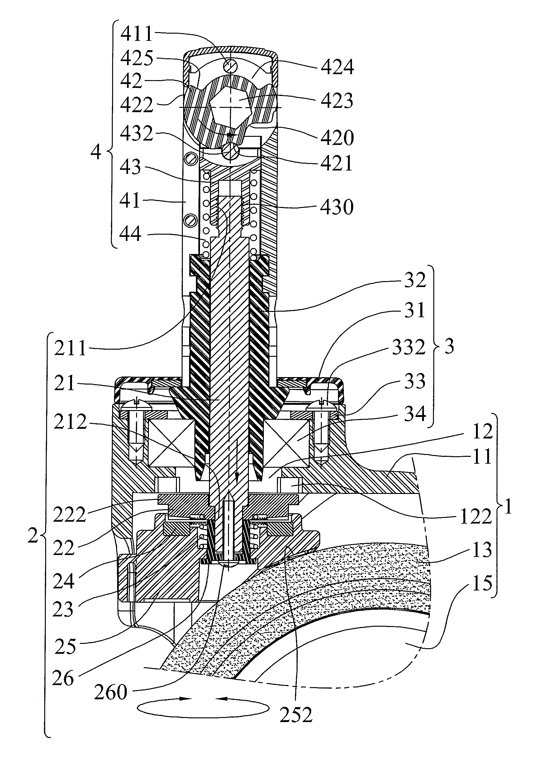
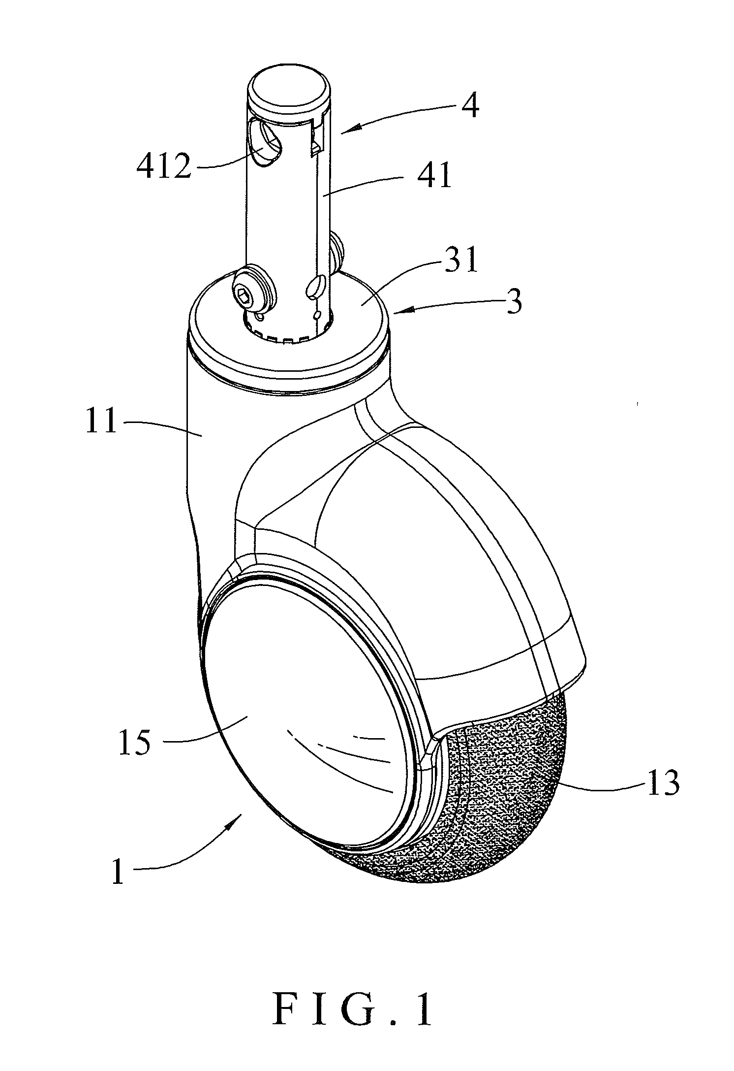
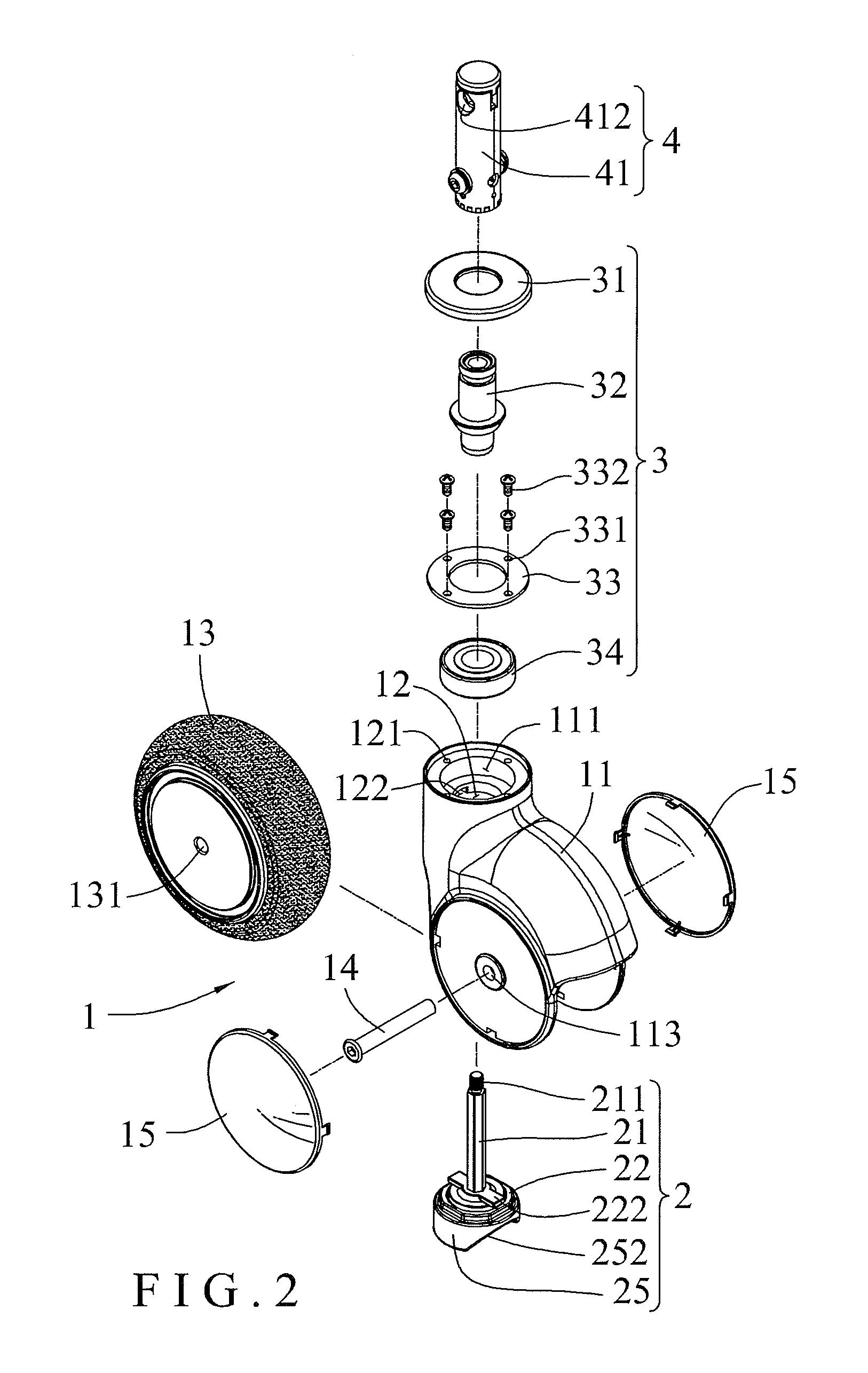
[0021]Referring to the drawings and initially to FIGS. 1-6, a castor assembly in accordance with the preferred embodiment of the present invention comprises a support unit 3, a frame unit 1 pivotally connected with the support unit 3, a brake unit 2 pivotally connected with the support unit 3 and detachably locked onto the frame unit 1 to releasably brake the frame unit 1, and an operation unit 4 mounted on the support unit 3 and connected with the brake unit 2 to drive the brake unit 2 relative to the frame unit 1.

[0022]The frame unit 1 includes a frame 11 having an upper end provided with a mounting hole 111, a locating flange 12 mounted in the mounting hole 111 of the frame 11 and having a bottom provided with a locating groove 122, a wheel 13 rotatably mounted on a lower end of the frame 11, a shaft 14 extended through the frame 11 and the wheel 13, and two side covers 15 mounted on two opposite sides of the frame 11 to cover the shaft 14.

[0023]The locating flange 12 and the mou...


PUM


Abstract

A castor assembly includes a support unit, a frame unit, a brake unit, and an operation unit. The frame unit includes a frame, a locating flange, and a wheel. The support unit includes a bearing, and an inner bushing. The brake unit includes a control shaft, a braking block, a lower toothed disk, an upper toothed disk, a locking block, and an elastic member. The operation unit includes a housing, a drive seat, a pressing roll, a cam block, and a restoring member. Thus, when the braking block presses the wheel to stop movement of the wheel, the upper toothed disk meshes with the lower toothed disk to lock the lower toothed disk and the braking block so that the wheel is locked and cannot be turned freely when the wheel is braked.

Description

BACKGROUND OF THE INVENTION[0001]1. Field of the Invention[0002]The present invention relates to a wheeled vehicle and, more particularly, to a castor assembly for a cart, trolley, chair, wheelchair and the like.[0003]2. Description of the Related Art[0004]A conventional castor assembly comprises a shaft, a mounting bracket pivotally mounted on the shaft and a wheel rotatably mounted on the mounting bracket. The shaft is mounted on the bottom of an object, such as a chair, cart and the like. In practice, when the castor assembly is moved, the wheel is rotated on the mounting bracket, and the mounting bracket is rotated on the shaft. Thus, the castor assembly is moved freely so as to support and move the object. However, the castor assembly does not have a braking function so that the object is not positioned in place exactly and stably, thereby causing inconvenience to the user.BRIEF SUMMARY OF THE INVENTION[0005]In accordance with the present invention, there is provided a castor a...

Claims


Application Information

Patent Timeline
Patent Type & Authority Applications(United States)
IPC IPC(8): B60B33/00
CPCB60B33/001B60B33/0021B60B33/0039B60B33/0049Y10T16/184B60B33/0081B60B33/021B60B33/025B60B33/0068
Inventor LIN, MING-HSIENYANG, FENG-HSICHEN, PO-LU
Owner SUNNY CASTORS
Why Eureka
Eureka Blog
Learn More