
Rolling-contact bearing containing solid lubricant therein

a technology of solid lubricant and rolling contact bearing, which is applied in the direction of needle bearings, shaft and bearings, rotary bearings, etc., can solve the problems of many manufacturing steps and troublesome working, and achieve the effect of higher hermetic properties

Active Publication Date: 2007-06-26
NIPPON THOMPSON
View PDF20 Cites 126 Cited by
  • Summary
  • Abstract
  • Description
  • Claims
  • Application Information

AI Technical Summary

Benefits of technology

[0011]The present invention, therefore, has as its primary object to overcome the problems as described just above and more particular to provide a rolling-contact bearing containing solid lubricant therein, in which a complete unitary molding comprised of a cage and more than one roller joined together with solid lubricant into a unitary part is incorporated between rolling element raceways of an inside and outside relatively rotating members, contrary to any conventional construction where the solid lubricant is sealed directly along the raceways coming into rolling contact with the rollers. Especially, the present invention provides a rolling-contact bearing containing solid lubricant therein, in which the complete unitary molding comprised of a cage and more than one roller joined together with solid lubricant is easily and surely made in such a way the rollers are partially exposed above an inside circular surface of the complete unitary molding, with only the help of difference in thermal expansion among an inside mold, outside mold and intermediate mold, and also ready for assembling with ease into the rolling element raceways.
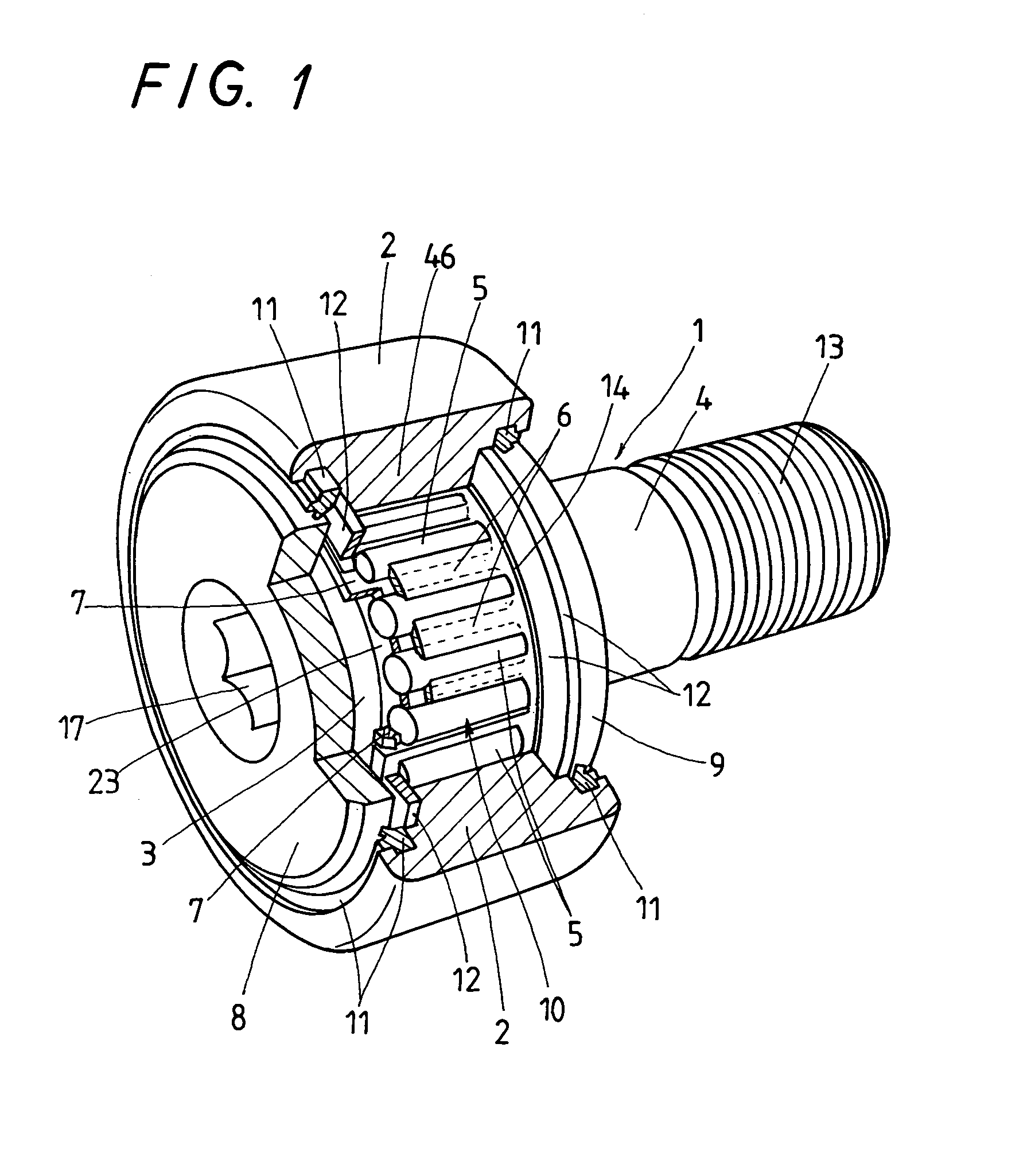
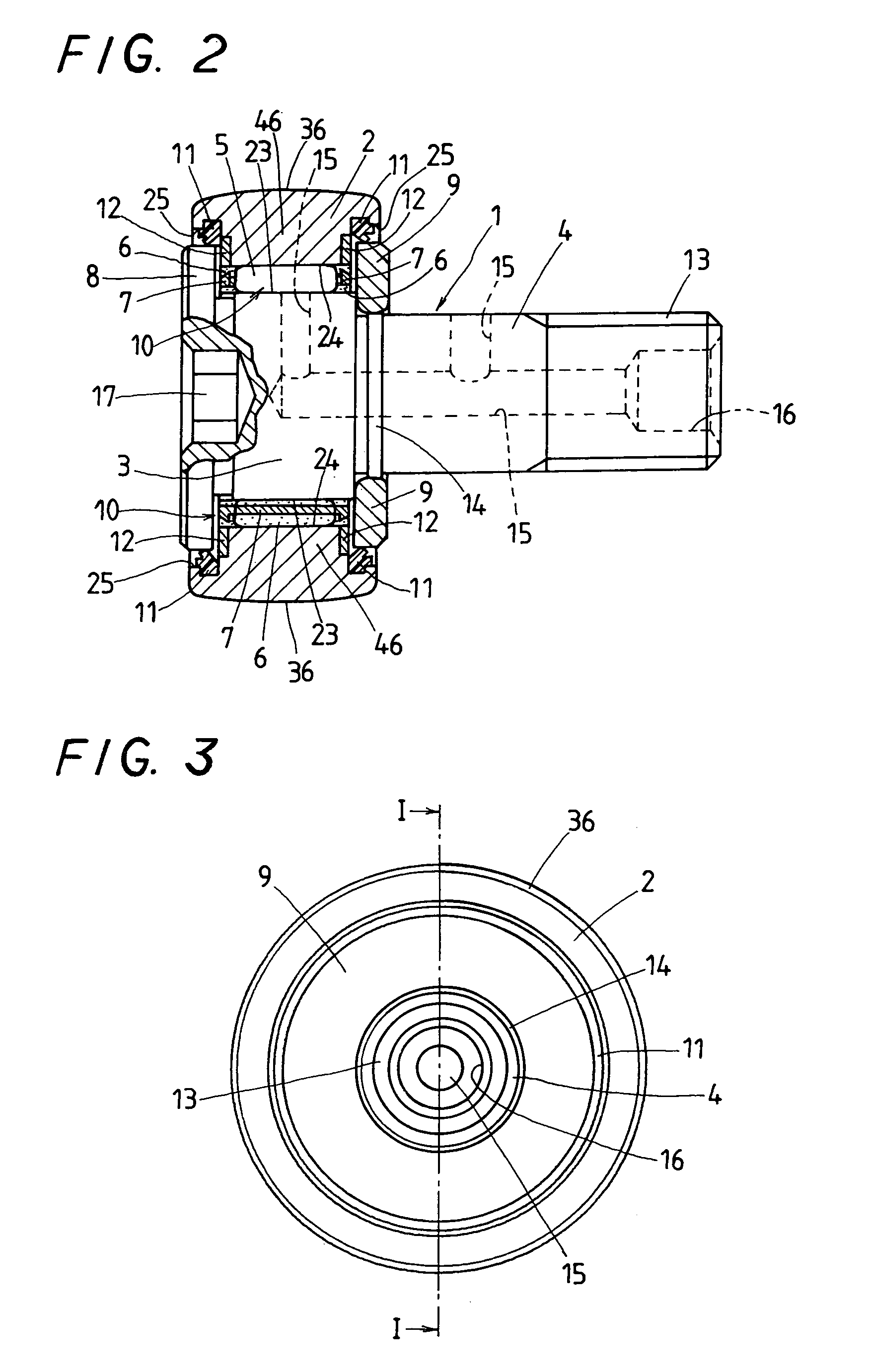
[0023]With the rolling-contact bearing containing solid lubricant therein constructed as stated earlier, the complete unitary molding, as made by solidification in the mold, which is given with the help of any difference in expansion by heat between an outside and intermediate molds, can be precisely formed precisely and most easily with rollers being exposed partially at their rolling surfaces above the inside and outside circular surfaces, especially inside circular surface of the complete unitary molding, but most enshrouded in the solid lubricant. The complete unitary molding provided according to the present invention makes it possible to continue supplying solid lubricant to the rollers, thereby making the rolling-contact bearing virtually maintenance-free. Moreover, no solid lubricant remains between the raceway around the outer ring or the inside rotating member such as the stud, inner ring or the like and the rolling surfaces of the rollers. Thus, the complete unitary molding does not have to cut any excess of solid lubricant away from both the inside and outside circular surfaces of the molding after the molding procedure thereof, which can make sure of smooth rolling motion of the rollers. The rolling-contact bearing having assembled the complete unitary molding therein can be made compact or slim in construction and maintenance-free virtually. Moreover, the stud or outer ring is allowed to have oil port therein, which serves to supply any lubricant consumed. The outer ring having an outside surface made in a part of sphere can conform well to any lopsided load. In the rolling-contact bearing containing solid lubricant therein according to the present invention, the complete unitary molding in which the cage, rollers and solid lubricant are all joined together into a single part contributes to rendering the rolling-contact bearing itself higher in hermetic property and ready for long-life services.

Problems solved by technology

With the prior cam follower constructed as stated earlier, the separator, although made of polymer allowing the lubricant oozing over the rollers, needs the troublesome working of fitting many rollers into the rectangular openings, one to each opening, to complete the cam follower.
The prior production method recited earlier, however, needs many manufacturing steps and several more chores including clamping overall the rolling-contact bearing between the mold halves.
Nevertheless, there still remains a major challenge to consider about how to make the complete unitary molding that is easy to handle the molding itself and simple to install the molding between any inside rotating member and an outer ring.

Method used


Image

  • Rolling-contact bearing containing solid lubricant therein
  • Rolling-contact bearing containing solid lubricant therein
  • Rolling-contact bearing containing solid lubricant therein

Examples


Embodiment Construction

[0034]Preferred embodiments of a rolling-contact bearing containing solid lubricant therein in accordance with the present invention will be explained hereinafter in detail with reference to the accompanying drawings. The rolling-contact bearing containing solid lubricant therein may be applied well to any rolling-contact bearing such as the stud-type roller bearing with tracking roller and so on, which is extensively employed for the cam-follower mechanisms or rolling-contact bearings for linear motion in printing machines, food processing machinery, liquid crystal display / semiconductor device manufacturing equipment, tool machines, industrial robots, office-automation machines, and so on. The rolling-contact bearing containing solid lubricant therein of the present invention features that a solid lubricant 6 to lubricate more than roller is placed between an inside relatively rotating member including an inside ring, stud or the like and an outside relatively rotating member such ...


PUM


Abstract

A cage, rollers and solid lubricant are all formed integrally into a complete unitary molding with using difference in thermal expansion in a mold. Assembling the complete unitary molding into the race in the rolling-contact bearing is made easier. The complete unitary molding is made such that the rollers remain exposed partially at their rolling surfaces above the inside circular surface of the complete unitary molding while the solid lubricant on the outside circular surface of the complete unitary molding is squeezed out from between the rolling surfaces of the rollers and the inside circular surface of the outside mold upon molding operation, thereby getting the rolling surfaces of the rollers exposed partially. The mold is composed of an outside mold, an inside mold and an intermediate mold, which is made of a substance larger in thermal expansion than other substance for the outside and inside molds.

Description

FIELD OF THE INVENTION[0001]The present invention relates to a standardized rolling-contact bearing of stud type for a tracking roller and, more particularly, to a rolling-contact bearing containing solid lubricant therein, in which more than one roller held in a cage is combined with solid lubricant into a complete unitary molding that is interposed between an outer and inner raceways.BACKGROUND OF THE INVENTION[0002]Conventionally, there is well known a rolling-element assembly used for rolling-contact bearings. An example of the rolling-element assemblies is disclosed in, for example Japanese Patent Laid-Open No. 2001-208084 in which more than one roller is held for rotation in a pocket in a cage and embedded in solid lubricant with a bearing circular surface thereof being exposed partially out of the solid lubricant. With the prior rolling-element assemblies of the sort recited earlier, however, the rollers are not combined with the cage into a unit and, therefore apt to come ap...

Claims


Application Information

Patent Timeline
IPC IPC(8): F16C33/66F16C33/56F16C33/76F16C13/00F16C19/44F16C33/46F16C33/62F16C33/64
CPCF16C13/006F16C19/44F16C33/56F16C33/6677F16C33/6696F16C33/565F16C33/6648F16C33/4611
Inventor KATO, MASATAKANISHIMATSU, TOSHIAKI
Owner NIPPON THOMPSON
Learn More