
Variable stroke-characteristic engine for vehicle

a vehicle and variable stroke technology, applied in the direction of engines, machines/engines, mechanical equipment, etc., can solve the problems of reducing the amount of heat dissipation, affecting the durability of the actuator, and the temperature of the actuator is known to rise, so as to improve the cooling

Inactive Publication Date: 2007-06-26
HONDA MOTOR CO LTD
View PDF6 Cites 9 Cited by
  • Summary
  • Abstract
  • Description
  • Claims
  • Application Information

AI Technical Summary

Benefits of technology

The present invention relates to a variable stroke-characteristic engine for a vehicle. The engine includes a first link connected to a piston, a second link connected to the first link or the second link and a crankshaft, a third link connected at one end to the first or second link and movably supported on an engine block through a control shaft, and an actuator for driving the control shaft. The actuator is connected to the end of the control shaft and is exposed on the outer surface of the engine block on the front side of the vehicle body. The actuator is exposed to traveling wind, which enhances the cooling effect and improves its durability. The actuator can be positioned on the front side of the engine block or the side opposite to the exhaust manifold, and a hydraulic pressure supply device can be placed on the front portion of the vehicle body opposed to the actuator to improve its reliability and durability. The actuator can be disposed at the axial end of the crankshaft or at a portion of the engine block on the front side of the vehicle body, and a switch valve can be placed on the front surface of the engine block at the end closer to the actuator to supply working oil to the actuator. The actuator can be inclined rearwards of the vehicle body to further enhance its cooling effect. These features improve the durability and reliability of the actuator and prevent any reduction in its operational responsiveness.

Problems solved by technology

However, in such an arrangement, it is impossible to apply traveling wind to the actuator, which results in a reduction in an amount of heat that is dissipated.
Also, the temperature of the actuator is known to rise, which affects the durability of the actuator.

Method used


Image

  • Variable stroke-characteristic engine for vehicle
  • Variable stroke-characteristic engine for vehicle
  • Variable stroke-characteristic engine for vehicle

Examples


Embodiment Construction

[0030]A preferred embodiment of the present invention will be described with reference to the accompanying drawings.

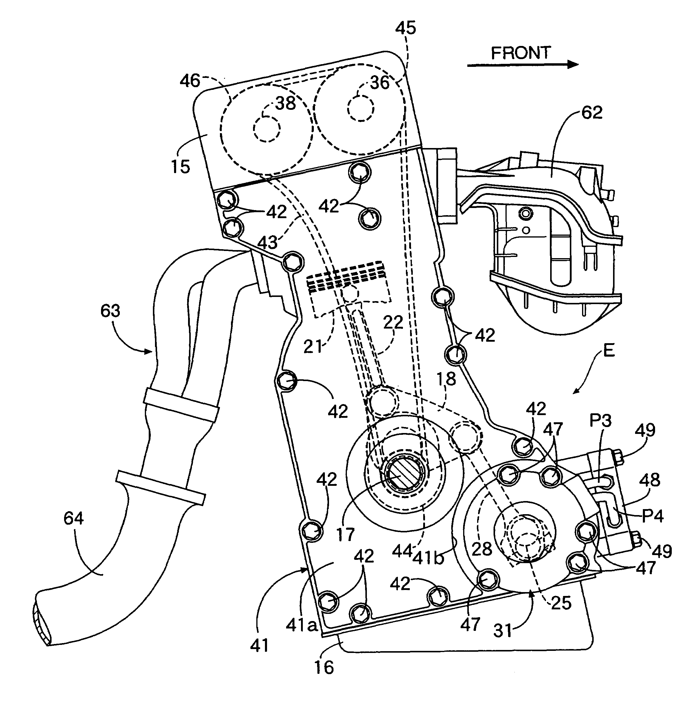
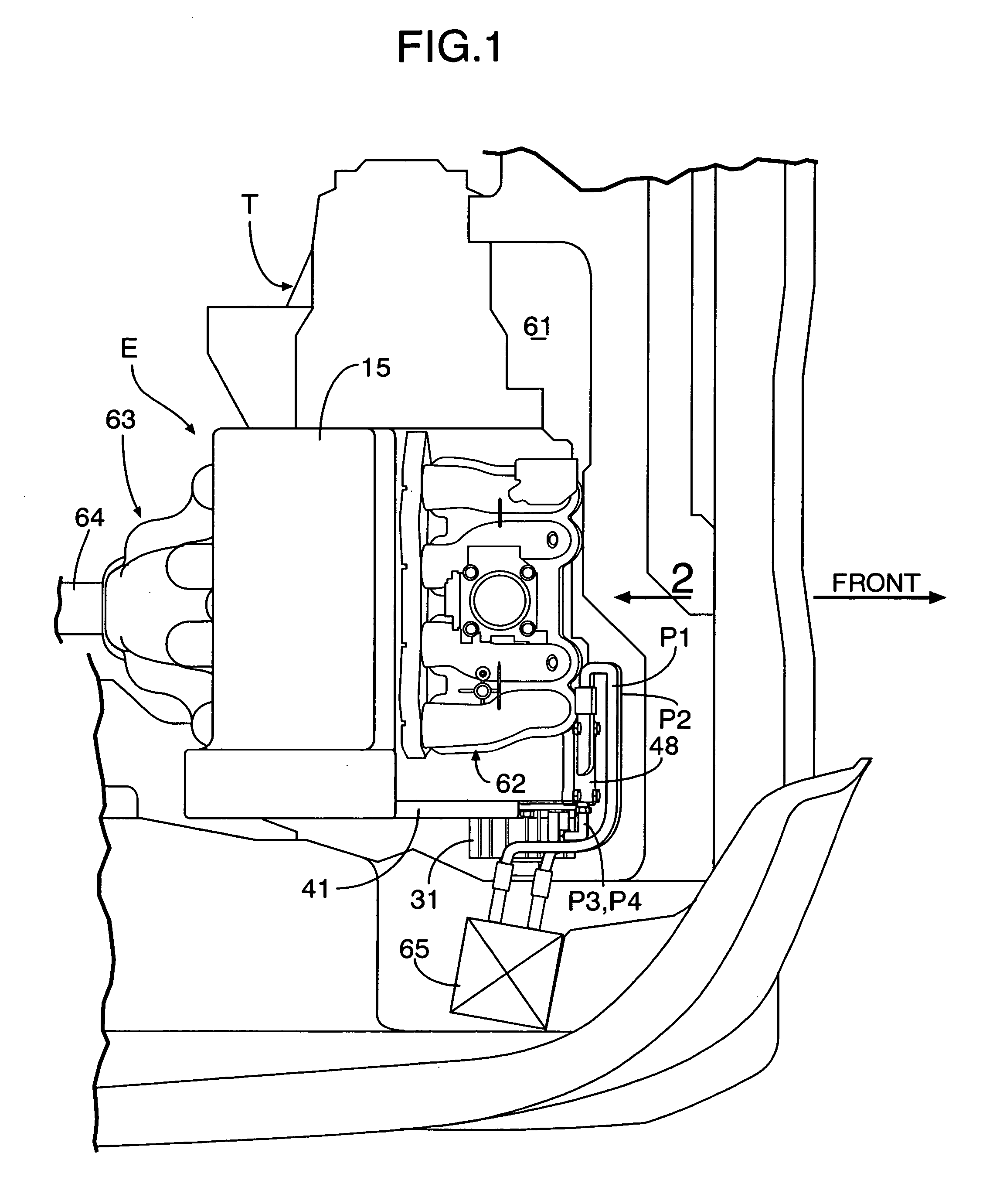
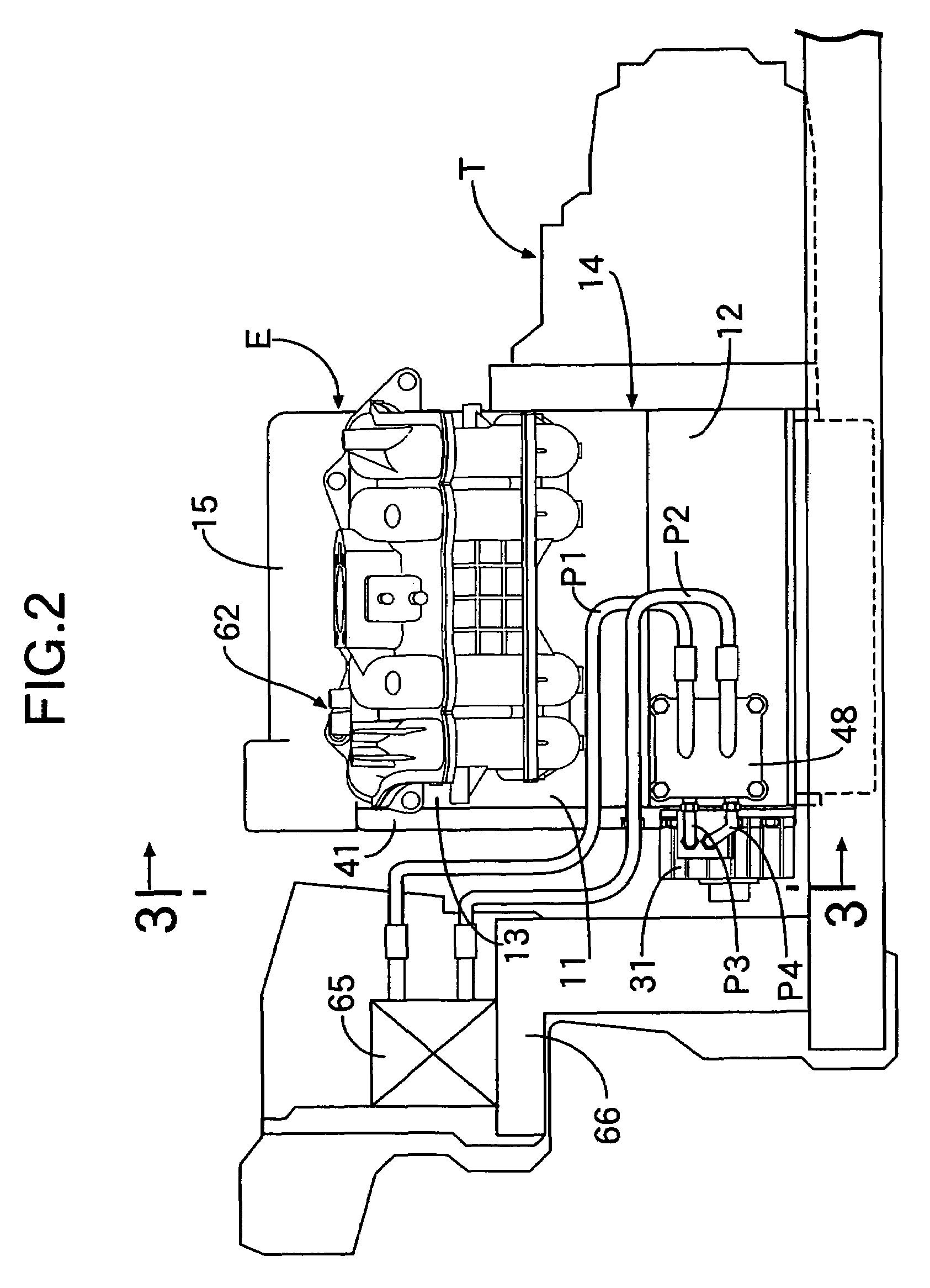
[0031]As shown in FIGS. 1 to 3, a variable compression-ratio engine E, which is one example of a variable stroke-characteristic engine wherein the position of a top dead center or a bottom dead center of a piston is changeable, is mounted at a sideward position in an engine room 61 in a front portion of a vehicle body of an automobile. A transmission T is coupled to a left side of the engine E. The engine E includes an engine block 14 to which a cylinder block 11, a crankcase 12 and a cylinder head 13 are coupled. A head cover 15 is coupled to an upper portion of the cylinder head 13. An oil pan 16 is coupled to a lower portion of the crankcase 12. The engine E is mounted in a rearward-inclining state, wherein an upper portion that is closer to the head cover 15 is located on a rear side of the vehicle body relative to a lower portion that is closer to the oil pan 16. ...


PUM


Abstract

In a variable stroke-characteristic engine for a vehicle, a control shaft and a control link are disposed on a front side of a vehicle body with respect to a crankshaft. An actuator for driving the control shaft is disposed on an outer surface of an engine block on the front side of the vehicle body. Thus, the actuator projects as much as possible from a position of the engine block toward the front side of the vehicle body so that traveling wind from ahead of the vehicle is effectively applied to the actuator to enhance the cooling effect. Hence, any temperature increase of the actuator is suppressed. Moreover, the actuator is disposed as far as possible from an exhaust manifold that is heated to a high temperature by the heat of an exhaust gas.

Description

RELATED APPLICATION DATA[0001]The present invention is based upon Japanese priority application No. 2004-368938, which is hereby incorporated in its entirety herein by reference.BACKGROUND OF THE INVENTION[0002]1. Field of the Invention[0003]The present invention relates to a variable stroke-characteristic engine for a vehicle, including a first link connected to a piston; a second link connected to the first link and a crankshaft; a third link connected at one end to the first link or the second link and movably supported at the other end on an engine block through a control shaft; and an actuator which drives the control shaft.[0004]2. Description of the Related Art[0005]Japanese Patent Application Laid-open Nos. 2004-156537 and 2003-322036 disclose a variable stroke-characteristic engine for a vehicle, having a crankshaft with a main journal rotatably supported in an engine block; a control shaft with a main journal supported for swinging in a predetermined angle range in the eng...

Claims


Application Information

Patent Timeline
Patent Type & Authority Patents(United States)
IPC IPC(8): F02B75/04F02D15/02
CPCF02B75/048
Inventor TANAKA, SHIGEKAZUYOSHIKAWA, TAICHIETO, KOICHISATO, HISASHIMAEZURU, AKINORI
Owner HONDA MOTOR CO LTD
Learn More