Monitoring system for fuel cell stack

a monitoring system and fuel cell technology, applied in secondary cell servicing/maintenance, electrochemical generators, instruments, etc., can solve the problems of severe consequences, voltage output of such electrodes will reach abnormal values, and the overall performance of the fuel cell stack would be downgraded, so as to achieve efficient and reliable means.

Inactive Publication Date: 2007-06-19
SHANGHAI SHENLI TECH CO LTD
View PDF3 Cites 0 Cited by
  • Summary
  • Abstract
  • Description
  • Claims
  • Application Information

AI Technical Summary

Benefits of technology

[0016]A main object of the present invention is to provide a monitoring system for a fuel cell stack as well as a huge group integrated fuel cell stacks for instantly diagnosing and alerting an abnormal operational condition thereof in an efficient and reliable way.
[0017]Another object of the present invention is to provide a monitoring system for fuel cell stack as well as a huge group of integrated fuel cell stacks for overcoming the above mentioned drawbacks by means of directly measuring the voltage output of each fuel cell unit.

Problems solved by technology

Therefore, when one of the individual fuel cells fails to operate, the overall performance of the fuel cell stack would be downgraded.
Especially, when an electrode is disruptive, the voltage output of such electrode will reach an abnormal value, such as a value close to zero, or even a negative value.
And more importantly, the extended service of such abnormal fuel cell unit would cause severe consequences.
However, in case the fuel cell stack to be monitored contains too many fuel cell units or there are several fuel cell stacks needed to be monitored simultaneously, such monitoring device would suffer some unavoidable drawbacks.
First of all, the RS485 communicating mode is vulnerable in reliability and inefficient in transmitting speed.
Unfortunately, such decoding circuits are rather bulky and not suitable to be used for large scale fuel cell stacks.
Third, since there is considerable number of measure lines, the leading wires for such monitoring system would be lengthy.
Fourth, the prolonged leading wires are susceptible to be interfered by surrounding environments thus worsening the stability and reliability of the fuel cell stack.
Finally, the assembly process of the monitoring system is rather complicated and awesome for common operators.

Method used


Image

  • Monitoring system for fuel cell stack
  • Monitoring system for fuel cell stack
  • Monitoring system for fuel cell stack

Examples


Embodiment Construction

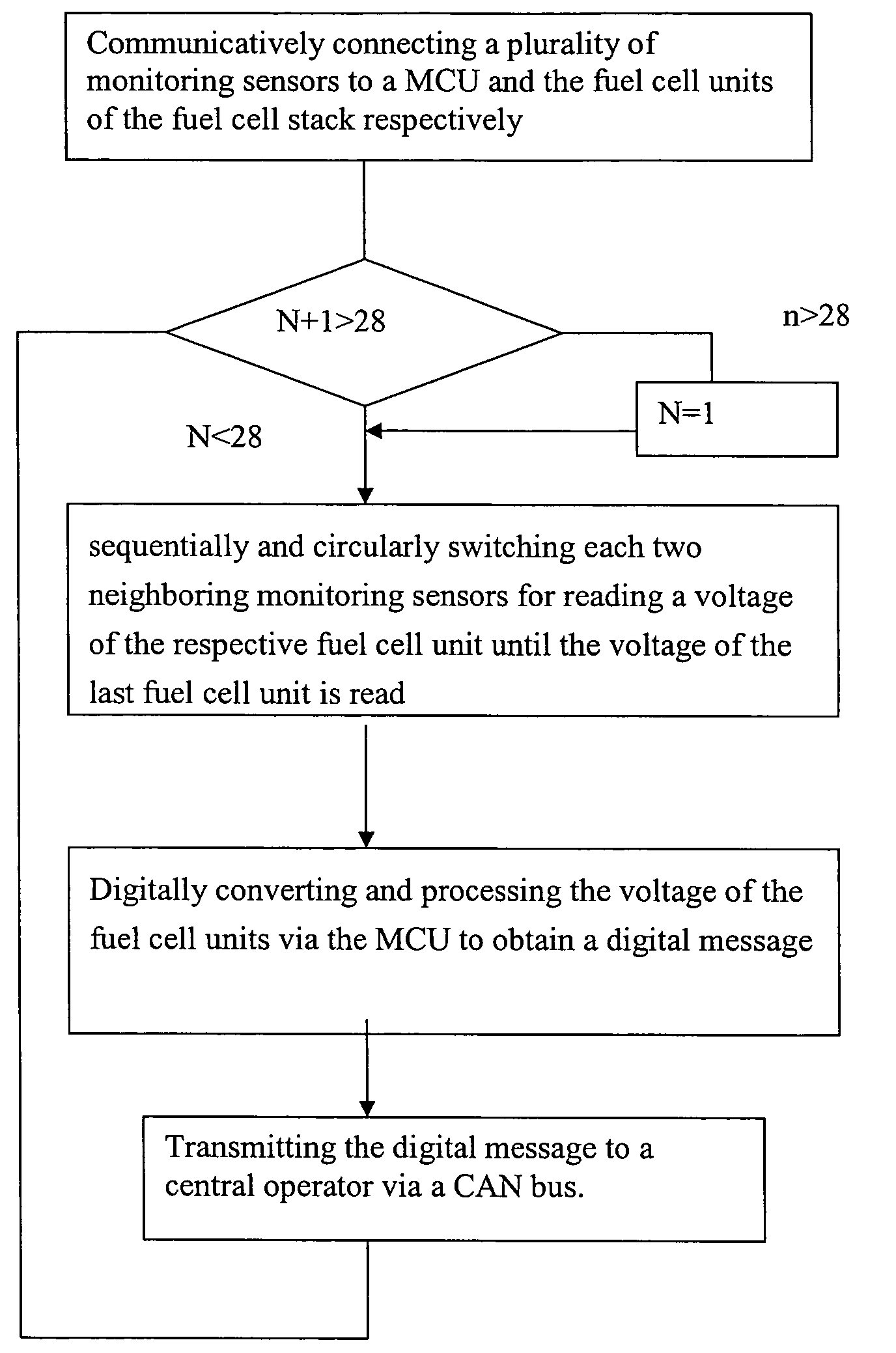
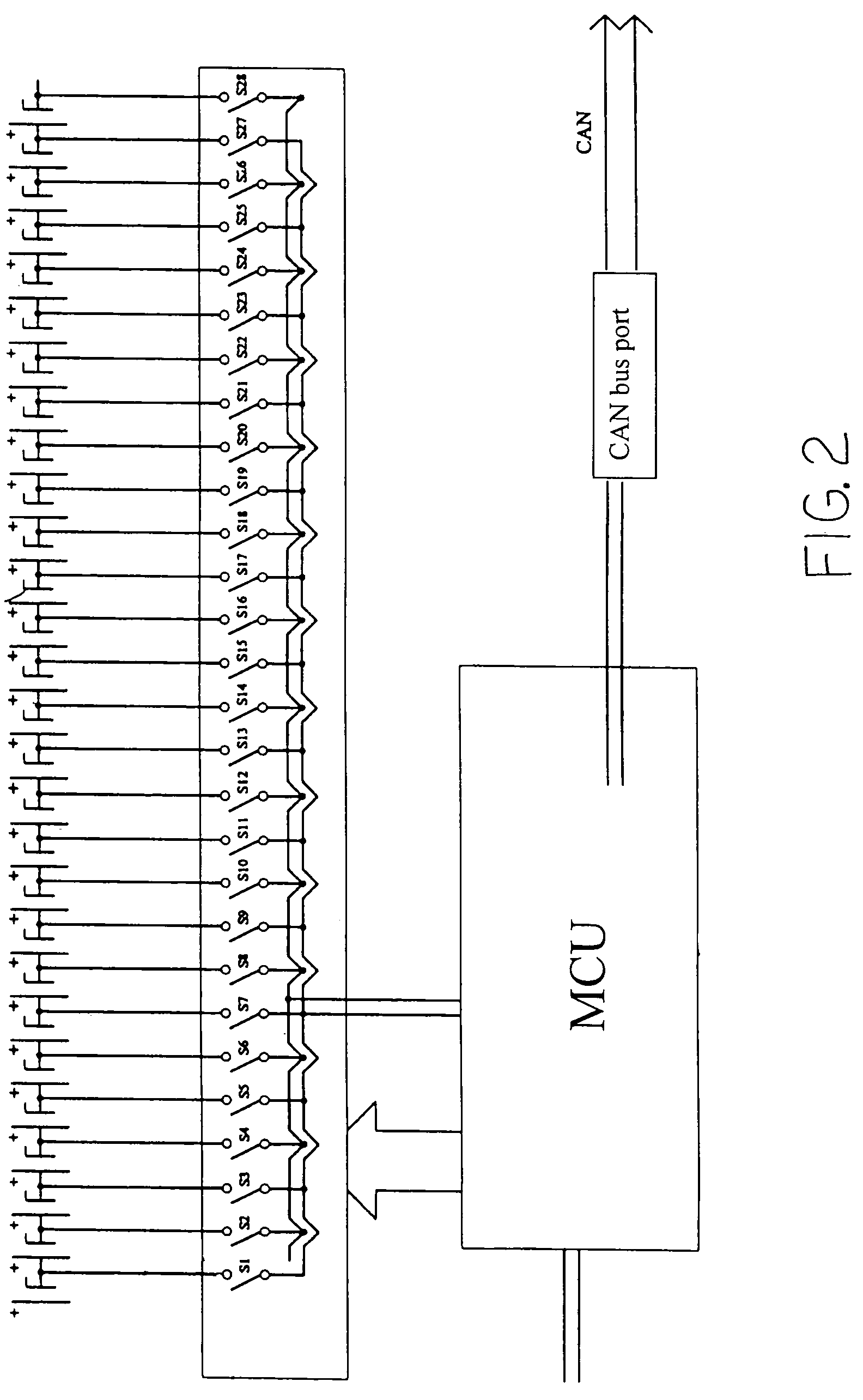
[0035]Referring to FIGS. 2 and 5 of the drawings, a monitoring system for monitoring an output voltage of a fuel cell stack 2 having a plurality of fuel cell units (fc1, fc2 . . . ) is illustrated, wherein each of the fuel cell units (fc1, fc2 . . . ) comprises at least an individual fuel cell such that the monitoring system is adapted to monitor the voltage of each individual fuel cell when each fuel cell unit (fc1, fc2 . . . ) contains one single fuel cell or the voltage of fuel cells when each fuel cell unit (fc1, fc2 . . . ) contains two or more fuel cells as a group.

[0036]According to the preferred embodiment of the present invention, the monitoring system 1 comprises a monitoring device 10 and a central operator 20.

[0037]The central operator 20 is electrically connected to the fuel cell stack 2 for administrating an operation of the fuel cell stack.

[0038]The monitoring device 10 comprises a plurality of monitoring sensors (S1, S2 . . . S28) adapted for electrically connecting ...


PUM


Abstract

A monitoring system includes a plurality of monitoring devices adjacently provided to a group of integrated fuel cell stacks for measuring a voltage of the fuel cell units. Each of the monitoring devices includes a plurality of monitoring sensors adapted for electrically connecting to a predetermined set of fuel cell units and a MCU (Micro-Chip-Unit) for sequentially and circularly switching each two neighboring monitoring sensors for reading the voltage of each respective fuel cell. A CAN bus is provided for electrically and collectively interconnecting the monitoring devices with a central operator which is arranged in such a manner that when said the voltage of the respective fuel cell unit exceeds a safety range, the central operator generates an alert signal for indicating an abnormal operation of the respective fuel cell.

Description

BACKGROUND OF THE PRESENT INVENTION[0001]1. Field of Invention[0002]The present invention relates to fuel cells, and more particularly to a monitoring system for fuel cell stack by monitoring the output voltage of each cell unit of the fuel cell stack to ensure the fuel cell stack working under an optimum condition.[0003]2. Description of Related Arts[0004]Electrochemical fuel cell is a kind of electrochemical energy conversion device which is capable of converting the hydrogen and oxidant into electrical energy. The core component of such device is the membrane electrode assembly (MEA). The MEA comprises a proton exchange membrane sandwiched by two porous sheets made of conductive material such as carbon tissue. Catalyst like metal platinum powder, adapted for facilitating the electrochemical reaction, are evenly and granularly provided on two carbon tissue sheets to form two catalytic interfaces. Furthermore, electrically conductible members are provided on two sides of the MEA to...

Claims


Application Information

Patent Timeline
Patent Type & Authority Patents(United States)
IPC IPC(8): G06F9/315
CPCH01M8/04559H01M8/04679H01M2008/1095Y02E60/50
Inventor FU, MINGZHUHU, LIQING
Owner SHANGHAI SHENLI TECH CO LTD
Why Eureka
Try Eureka