Relative and absolute calibration for dosimetric devices
a dosimetric device and relative and absolute calibration technology, applied in radiation therapy, instruments, therapy, etc., can solve the problems of increasing the cost and time consuming of the calibration process, and requiring additional equipment and time to gather data
- Summary
- Abstract
- Description
- Claims
- Application Information
AI Technical Summary
Benefits of technology
Problems solved by technology
Method used
Image
Examples
first embodiment
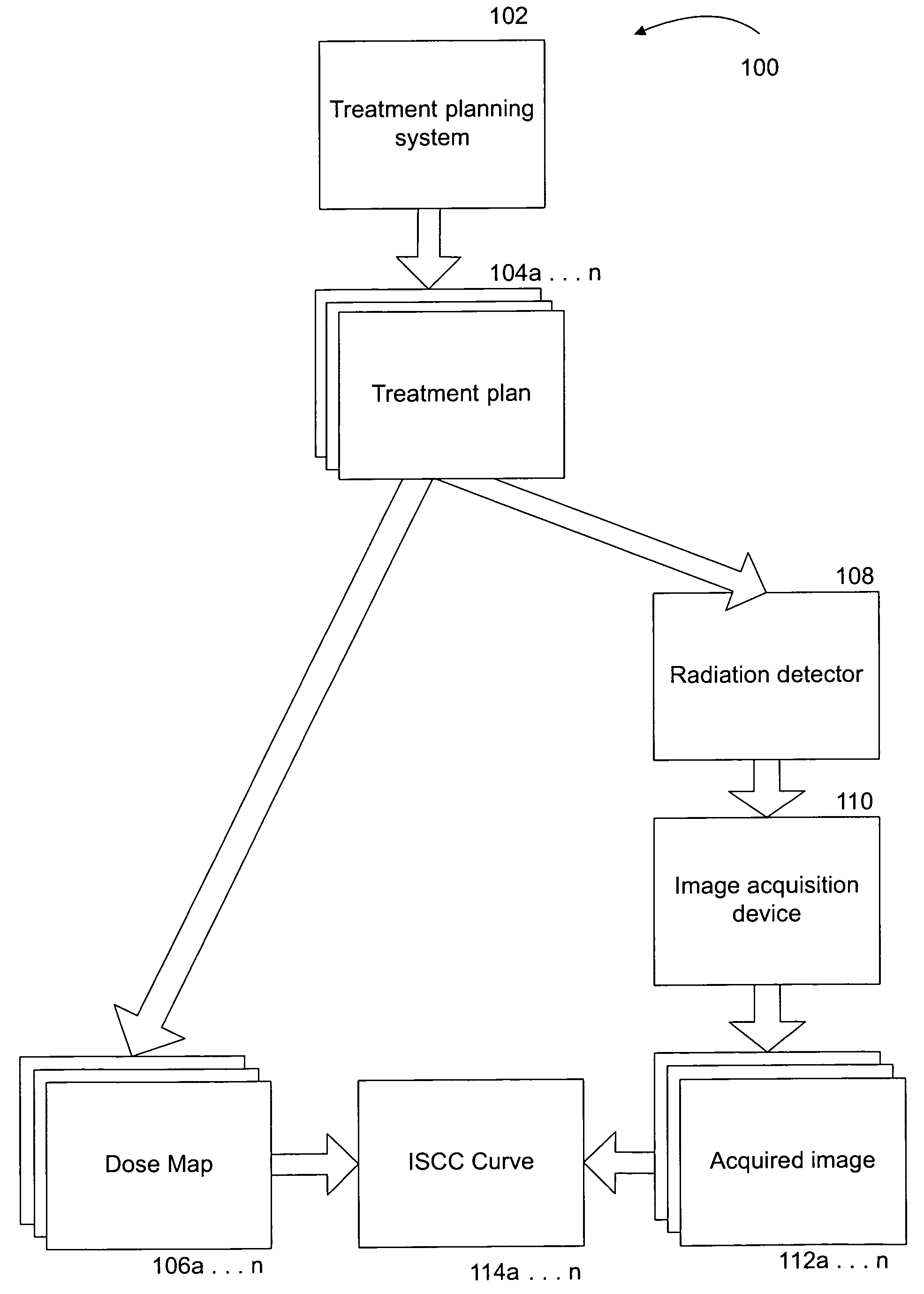
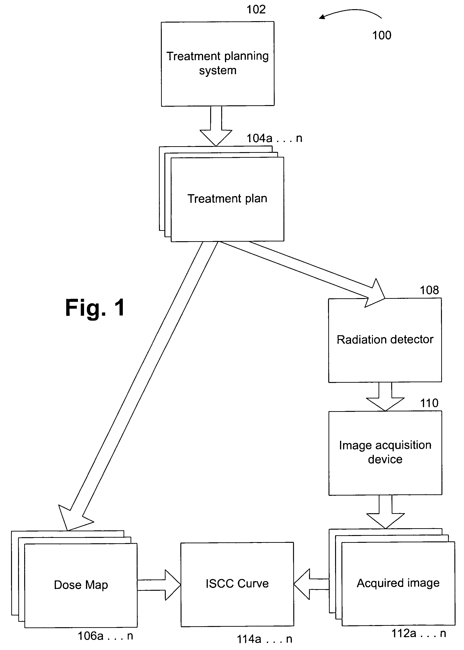
[0058]In a first embodiment, at step 312 dose map 106 is divided into small geometric areas. An example of a dose map 106 divided into small geometric areas (and after a statistical function has been applied to the areas, as described below) is shown in FIG. 7A. In one embodiment, the geometric areas are rectangles (or cubes for 3D images) that each include one percent of the area of the dose map 106. It should be noted that the geometric areas of the image may or may not be contiguous and may or may not physically overlap depending on the specific images employed.
second embodiment
[0059]In a second embodiment, at step 312 the dose levels on dose map 106 are divided into dose ranges. These dose ranges may or may not be contiguous and may or may not overlap. In one embodiment each dose range covers 1% of the total dose range on the plan image. That is, each 1% increment covers the range from 0 to the maximum dose on dose map 106 on a scale of 0 to 100. For each range of pixels in the dose curve a statistical measure such as the mean or the median is calculated. That is, the process finds all the pixels in each dose range on the plan image, i.e., dose map 106, and takes the mean (or median or some other measure of central tendency) of those pixels. An index locating the pixels on the registered images in each range is maintained.
third embodiment
[0060]In yet a third embodiment, at step 312, dose map 106 is divided into sub-regions such as the geometric areas described above comprising a percentage of the area of dose map 106. Dose map 106 is then translated into what is referred to as “column format.” It should be understood that use of column format is optionally employed for the sake of simplifying the process but that steps 312 and the steps following step 312 could be practiced without representing dose map 106 and acquired image 112 in column format. An example of a dose map 106 in column format is shown in FIG. 9A. Individual sub-regions of the dose map 106 shown in FIG. 6A are represented in individual columns of the image shown in FIG. 9A.
[0061]In the first embodiment discussed with reference to step 312, at step 314 pixels are located on the acquired image 112 that correspond to each geometric area of dose map 106, defined as described above with respect to step 312. Dose map 106 and acquired image 112 may optional...
PUM
 Abstract
Description
Claims
Application Information
 - R&D
- Intellectual Property
- Life Sciences
- Materials
- Tech Scout
- Unparalleled Data Quality
- Higher Quality Content
- 60% Fewer Hallucinations
Browse by: Latest US Patents, China's latest patents, Technical Efficacy Thesaurus, Application Domain, Technology Topic, Popular Technical Reports.
© 2025 PatSnap. All rights reserved.Legal|Privacy policy|Modern Slavery Act Transparency Statement|Sitemap|About US| Contact US: help@patsnap.com


