
Electrical switching device, relay and electrical apparatus comprising same

a switching device and relay technology, applied in the direction of relays, magnets, magnets, etc., can solve the problems of difficult integration of switching devices in electrical apparatuses of small dimensions able to be actuated manually, large temperature rise of contact blocks, and general bulky known devices, so as to reduce dimensions or volume, good electric current conduction, and good electric circuit switching or interruption

Inactive Publication Date: 2007-06-19
SCHNEIDER ELECTRIC IND SAS
View PDF5 Cites 14 Cited by
  • Summary
  • Abstract
  • Description
  • Claims
  • Application Information

AI Technical Summary

Benefits of technology

The invention is a switching device that allows for good electrical current conduction, has a small size, and can change between stable positions quickly. It includes a first part with a magnetizable element and a first contact zone, a second movable part with a magnetizable element and a second contact zone, and electromagnetic actuating means acting on the second movable part to change its stable position. The device can be controlled by electrical pulses and has permanent magnets with strong magnetic attraction. It can be fixed in a flexible way and has multiple contact zones that can be opened or closed simultaneously. The device is designed to have a compact size and can be used in electrical apparatuses.

Problems solved by technology

When the currents to be switched are strong, for example several Amperes, known devices are generally bulky.
In addition, the contact blocks have a large temperature rise and the magnetic circuits have to exert strong forces to move the movable parts.
Such switching devices are difficult to integrate in electrical apparatuses of small dimensions able to be actuated manually.

Method used


Image

  • Electrical switching device, relay and electrical apparatus comprising same
  • Electrical switching device, relay and electrical apparatus comprising same
  • Electrical switching device, relay and electrical apparatus comprising same

Examples


Embodiment Construction

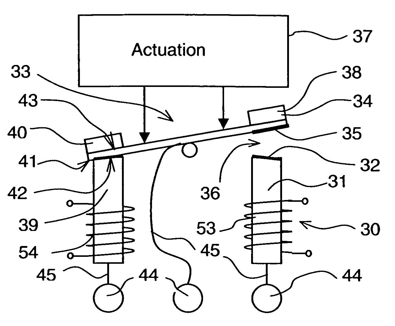
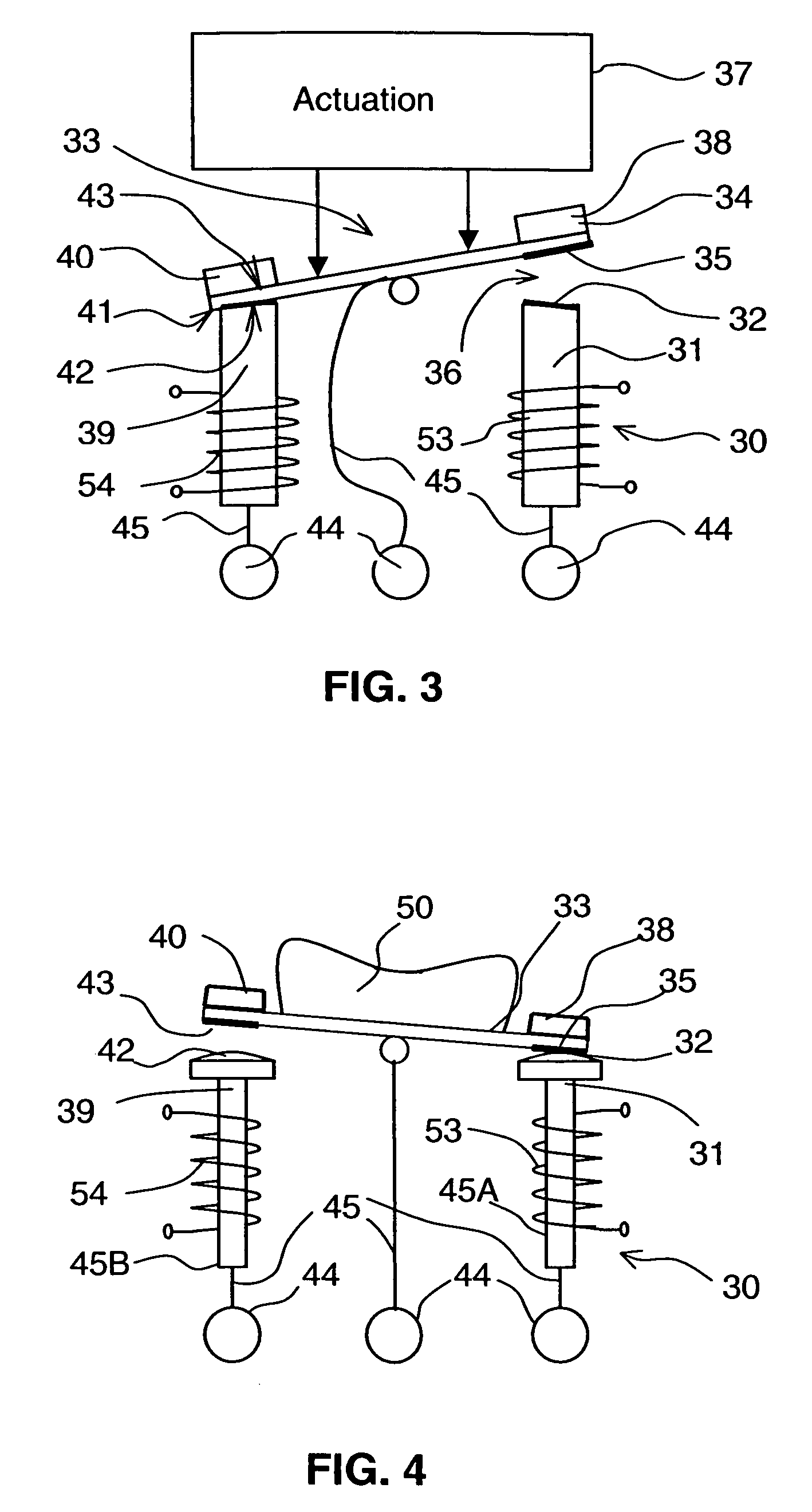
[0065]In a device according to an embodiment of the invention represented in FIG. 3, a first, preferably fixed, part 30 comprises a first magnetizable element 31 and a first contact zone 32 associated with said first magnetizable element 31, and a second movable part 33 comprises a second magnetic element 34 and a second contact zone 35 associated with said second magnetic element 34. Said second movable part 33 has at least a first stable position to keep a first electrical contact 36 closed between the first and second contact zones 32 and 35 and a second stable position to keep said first electrical contact open. Actuating means 37 able to be electromagnetic, and possibly manual or mechanical, enable action to be performed on the second movable part to make it change position. The first or second magnetic element comprises at least one permanent magnetization part to keep the first contact closed and to exert a contact pressure between the first and second contact zones.

[0066]The...


PUM

PropertyMeasurementUnit
volumeaaaaaaaaaa
magnetizableaaaaaaaaaa
magneticaaaaaaaaaa

Abstract

The electrical switching device comprises at least a first part comprising at least a first magnetizable element and a first contact zone associated with said first magnetizable element, and at least a second movable part comprising at least a second magnetic element and a second contact zone associated with said second magnetic element. The first or second magnetic element comprises at least one permanent magnetization part to keep the first electrical contact closed and to exert a contact pressure between the first and second contact zones when the movable part is in a first stable position. The electromagnetic relay and / or electrical apparatus comprise electrical contact inputs and control inputs connected to a switching device comprising electromagnetic control coils.

Description

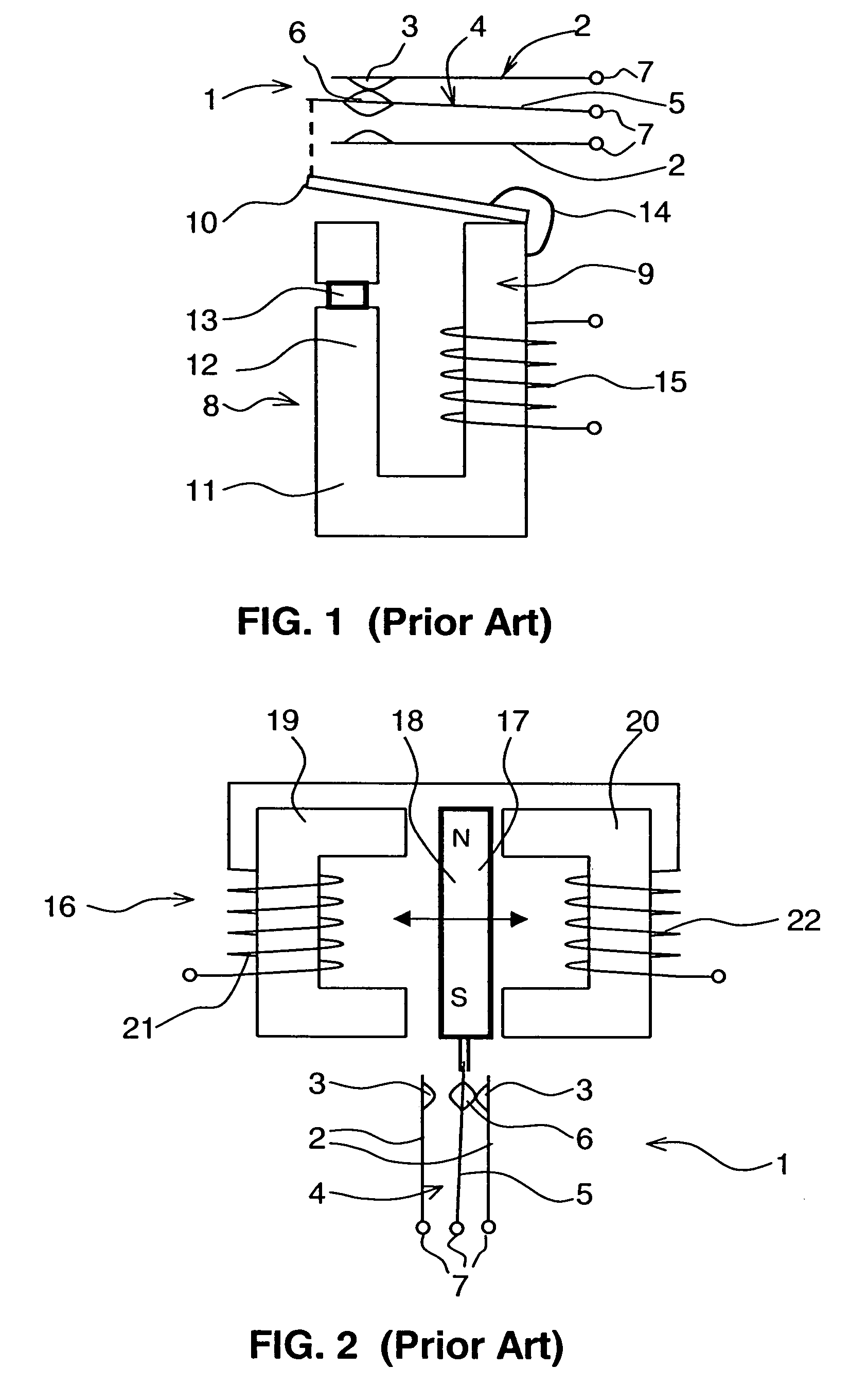
BACKGROUND OF THE INVENTION[0001]The invention relates to an electrical switching device comprising at least one electrical contact able to be kept in a stable position by magnetic means. The invention also relates to an electromagnetic relay with at least two stable states comprising at least a first and a second electrical contact inputs, control inputs, and at least one such switching device. The invention also relates to an electrical apparatus comprising at least a first and a second electrical contact input, and at least one such switching device.STATE OF THE ART[0002]Known switching devices, integrated in particular in relays and electrical switchgear apparatuses such as switches, comprise electrical contacts controlled in particular by a manual control means or an electromagnetic coil. Generally speaking, the electrical contacts comprise a fixed part and a movable part to open or close an electric circuit. The electrical contacts are kept in an open or closed position in cer...

Claims


Application Information

Patent Timeline
Patent Type & Authority Patents(United States)
IPC IPC(8): H01H9/00H01F7/00H01F7/08H01H1/54H01H51/01
CPCH01H1/54H01H51/01H01H2001/545H01H2036/0086
Inventor BATTEUX, PIERRE
Owner SCHNEIDER ELECTRIC IND SAS
Learn More