
Method to create hierarchical modulation in OFDM

a hierarchical modulation and digital audio radio technology, applied in the field of digital data transmission in satellite digital audio radio, can solve the problems that the hierarchical modulation scheme has not been envisioned for use in the sdar system, and achieve the effects of increasing the amount of digital data, increasing the amount of data, and enhancing the performance of the receiver

Active Publication Date: 2007-06-12
APTIV TECH LTD
View PDF12 Cites 42 Cited by
  • Summary
  • Abstract
  • Description
  • Claims
  • Application Information

AI Technical Summary

Benefits of technology

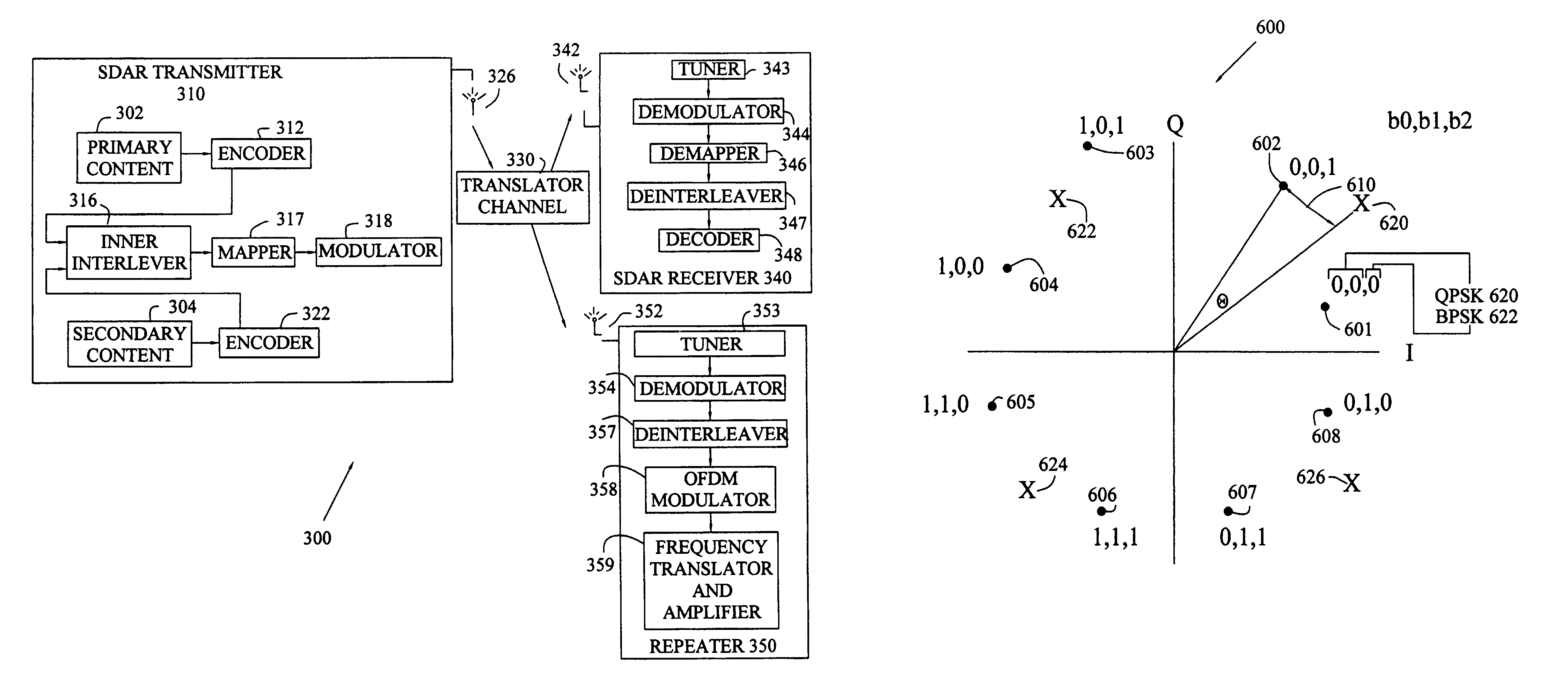
The present invention provides an apparatus and method for increasing the amount of digital data that may be transmitted from communication satellites to receivers in SDAR systems. This is achieved by introducing the use of hierarchical modulation schemes, which has not been previously envisioned for use in SDAR systems. The invention increases the amount of data that may be transmitted in SDAR systems and enables the enhanced performance of the receivers that receive the satellite-transmitted signals in SDAR systems. The invention includes a transmitter, a receiver, and a method for transmitting data using an OFDM transmission system. The transmitter generates an OFDM signal based on input data and introduces variations in the signal to increase the amount of data transmitted. The receiver demodulates the modified OFDM signal and detects the input data using a detector. The invention also includes an introducing step that may include introducing an additional phase offset or amplitude offset in the OFDM signal.

Problems solved by technology

While hierarchical modulation schemes have been previously used in other data transmission applications (e.g., Digital Video-Broadcasting-Terrestrial [DVB-T] and DVB-Satellite [DVB-S] systems), until now, such hierarchical modulation schemes have not been envisioned for use in SDAR systems.

Method used


Image

  • Method to create hierarchical modulation in OFDM
  • Method to create hierarchical modulation in OFDM
  • Method to create hierarchical modulation in OFDM

Examples


Embodiment Construction

[0024]The embodiments disclosed below are not intended to be exhaustive or limit the invention to the precise forms disclosed in the following detailed description. Rather, the embodiments are chosen and described so that others skilled in the art may utilize their teachings.

[0025]For the purposes of the present invention, certain terms shall be interpreted in accordance with the following definitions.

[0026]Baseband: A signal whose frequency content is in the vicinity of direct current (DC).

[0027]Carrier: A single frequency electromagnetic wave the modulations of which are used as communications signals.

[0028]Channel: A propagation medium for communication such as a path along which information in the form of an electrical signal passes (e.g., wire, air, water).

[0029]Data rate: The amount of data, or number of symbols, which may be transmitted on a signal per a unit of time.

[0030]Detector: A circuit that is capable of determining the content of a signal.

[0031]Downconvert: To convert...


PUM


Abstract

The present invention involves a method for transmitting data using an orthogonal frequency division multiplex (OFDM) transmission system, such as over a terrestrial network used in satellite digital audio radio. A OFDM signal is generated based on first input data. A variation is introduced in the OFDM signal based on second input data to generate a modified OFDM signal which is transmitted. The modified OFDM signal is decoded by performing a demodulation of the modified OFDM signal then a first and second detection to obtain the first input data and the second input data. The introduction of a variance may include introducing an additional phase offset across adjacent OFDM sub-carriers, across adjacent OFDM symbols, an additional phase offset in the OFDM signal, an additional amplitude offset in the OFDM signal, an additional amplitude augmentation in the OFDM signal, and / or a second variation in the first OFDM signal based on third input data.

Description

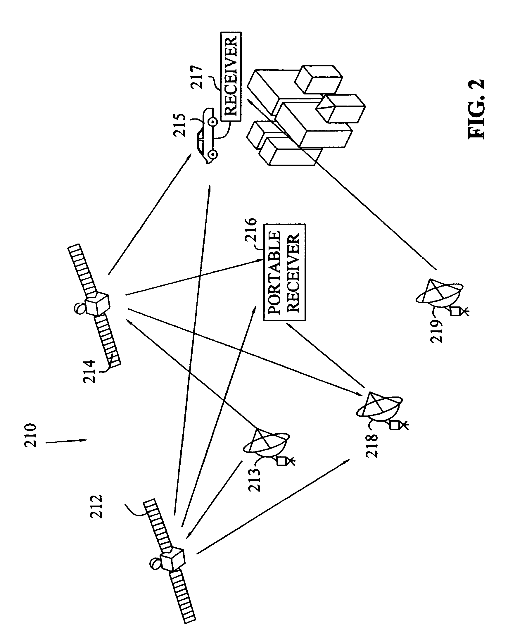
[0001]This application claims the benefit of U.S. Provisional Patent Application No. 60 / 525,616 filed on Nov. 26, 2003.TECHNICAL BACKGROUND[0002]The present invention generally relates to the transmission of digital data, and more particularly, to the transmission of digital data in a satellite digital audio radio (“SDAR”) system.BACKGROUND OF THE INVENTION[0003]In October of 1997, the Federal Communications Commission (FCC) granted two national satellite radio broadcast licenses. In doing so, the FCC allocated twenty-five (25) megahertz (MHz) of the electromagnetic spectrum for satellite digital broadcasting, twelve and one-half (12.5) MHz of which are owned by XM Satellite Radio, Inc. of Washington, D.C. (XM), and 12.5 MHz of which are owned by Sirius Satellite Radio, Inc. of New York City, N.Y. (Sirius). Both companies provide subscription-based digital audio that is transmitted from communication satellites, and the services provided by these and other SDAR companies are capable...

Claims


Application Information

Patent Timeline
Patent Type & Authority Patents(United States)
IPC IPC(8): H04K1/10H04L27/28H04H1/00H04H20/28H04H20/42H04H20/51H04H20/74H04H40/90H04L1/00H04L5/16H04L27/18H04L27/26H04L27/34
CPCH04H20/28H04H20/51H04H20/74H04H40/90H04L1/005H04L1/0066H04L1/0071H04L1/208H04L27/183H04L27/2602H04L27/3488H04H20/42H04L27/2626H04L27/2647
Inventor WALKER, GLENN A.DIBIASO, ERIC A.HIATT, JR., MICHAEL L.
Owner APTIV TECH LTD
Learn More