
Extendable spar buoy sea-based communication system

a communication system and spar buoy technology, applied in the direction of subaqueous/subterranean adaption, special-purpose vessels, vessel construction, etc., can solve the problems of increased probability of submarine detection, increased deployment of submarine sails, and increased detection consequences. , to achieve the effect of stable platform

Active Publication Date: 2007-06-05
RAYTHEON CO
View PDF27 Cites 25 Cited by
  • Summary
  • Abstract
  • Description
  • Claims
  • Application Information

AI Technical Summary

Benefits of technology

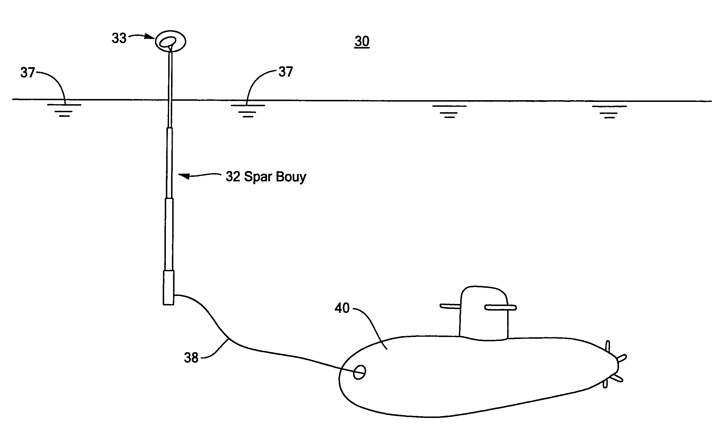
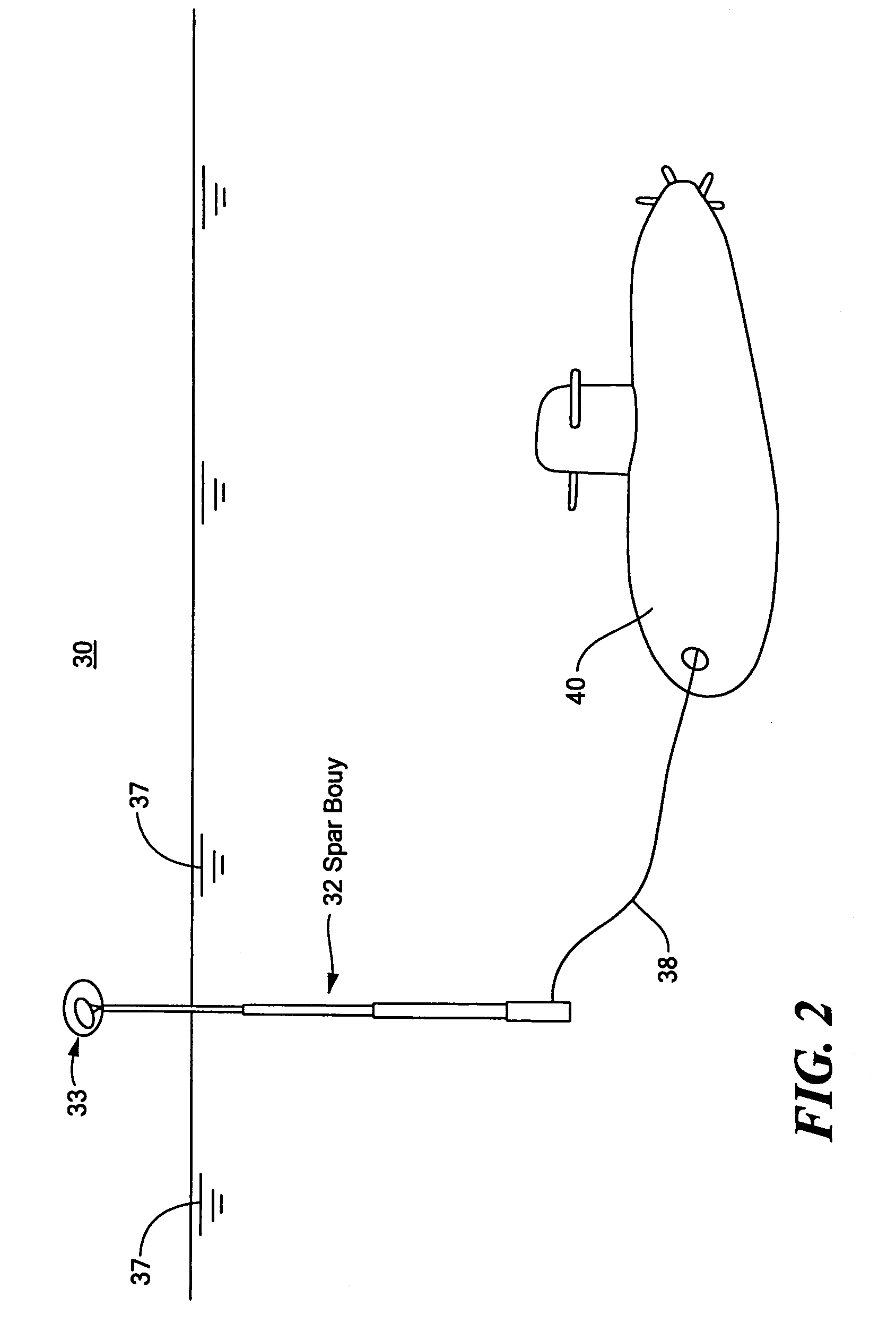
[0010]It is therefore an object of this invention to provide an improved sea-based communication system including an extendable spar buoy for providing a stable platform for a variety of communications devices or communication subsystems.
[0011]It is a further object of this invention to provide an improved sea-based communication system including an extendable spar buoy which allows for more efficient packaging of communication subsystems when stowed.
[0012]It is a further object of this invention to provide an improved sea-based communication system including an extendable spar buoy which can be launched from an underwater vessel such as a submarine while submerged through existing launching mechanisms.
[0013]It is a further object of this invention to provide an improved sea-based communication system including an extendable spar buoy which provides ample room for a compacted and expandable communication subsystem payload such that an underwater vessel such as a submarine may transmit and receive communications at depth and speed without compromising the location or operation of the underwater vessel.
[0014]It is a further object of this invention to provide an improved sea-based communication system including an extendable spar buoy which provides a platform for real time, high bandwidth satellite signal connection to an underwater vessel at depth and speed.
[0016]It is a further object of this invention to provide an improved sea-based communication system including an extendable spar buoy at relatively low cost and which is expendable.

Problems solved by technology

However, in the littorals or coastal regions near the sea surface, at slow speed, the probability of the submarine being detected increases and the consequences of detection are magnified.
However, deployment from the submarine sail has several drawbacks.
The limited length of the mast requires that the submarine operate at relatively shallow periscope depths for extended periods of time.
Thus, the safety of the mission and the submarine can be compromised.
Finally, the size (and hence, data rate) of retractable mast mounted SATCOM antennas are limited.
Such systems, however, typically have a number of disadvantages.
This limits the life of the battery that powers the UUV.
To achieve these requirements, a moderately large UUV is required, at high cost.
Additionally, recovery of an expensive and relatively large UUV diverts the submarine from its primary mission, and incurs additional risk of detection.
Traditional spar buoy designs are typically very large, stiff floating platforms comprising a large mass with significant righting moments.
A surface floating buoy, even with deployed outriggers, also has disadvantages especially if used for communications purposes.
It provides a poor platform for a stabilized antenna that must maintain its beam on a satellite in rough seas and high winds.
These factors make a surface floating buoy too large for the intended purposes.
Frequent release and retrieval activity produces acoustic signatures and increase the probability of detection, which is undesirable.
Also, the system does not provide wideband communications at depth and speed because the buoy will reach the surface only if neither depth nor speed is excessive.
Moreover, the size of the antenna that can be enclosed in the top of the retrievable buoy is too small to receive some types of communications such as wide-band GBS reception.
In addition, the motion of the submarine only allows for data gathering until the data and recovery cable is depleted, which is only a few minutes due to the limited length of cable available because the cable must be strong enough to retrieve the retractable buoy.

Method used


Image

  • Extendable spar buoy sea-based communication system
  • Extendable spar buoy sea-based communication system
  • Extendable spar buoy sea-based communication system

Examples


Embodiment Construction

[0041]Aside from the preferred embodiment or embodiments disclosed below, this invention is capable of other embodiments and of being practiced or being carried out in various ways. Thus, it is to be understood that the invention is not limited in its application to the details of construction and the arrangements of components set forth in the following description or illustrated in the drawings. If only one embodiment is described herein, the claims hereof are not to be limited to that embodiment. Moreover, the claims hereof are not to be read restrictively unless there is clear and convincing evidence manifesting a certain exclusion, restriction, or disclaimer.

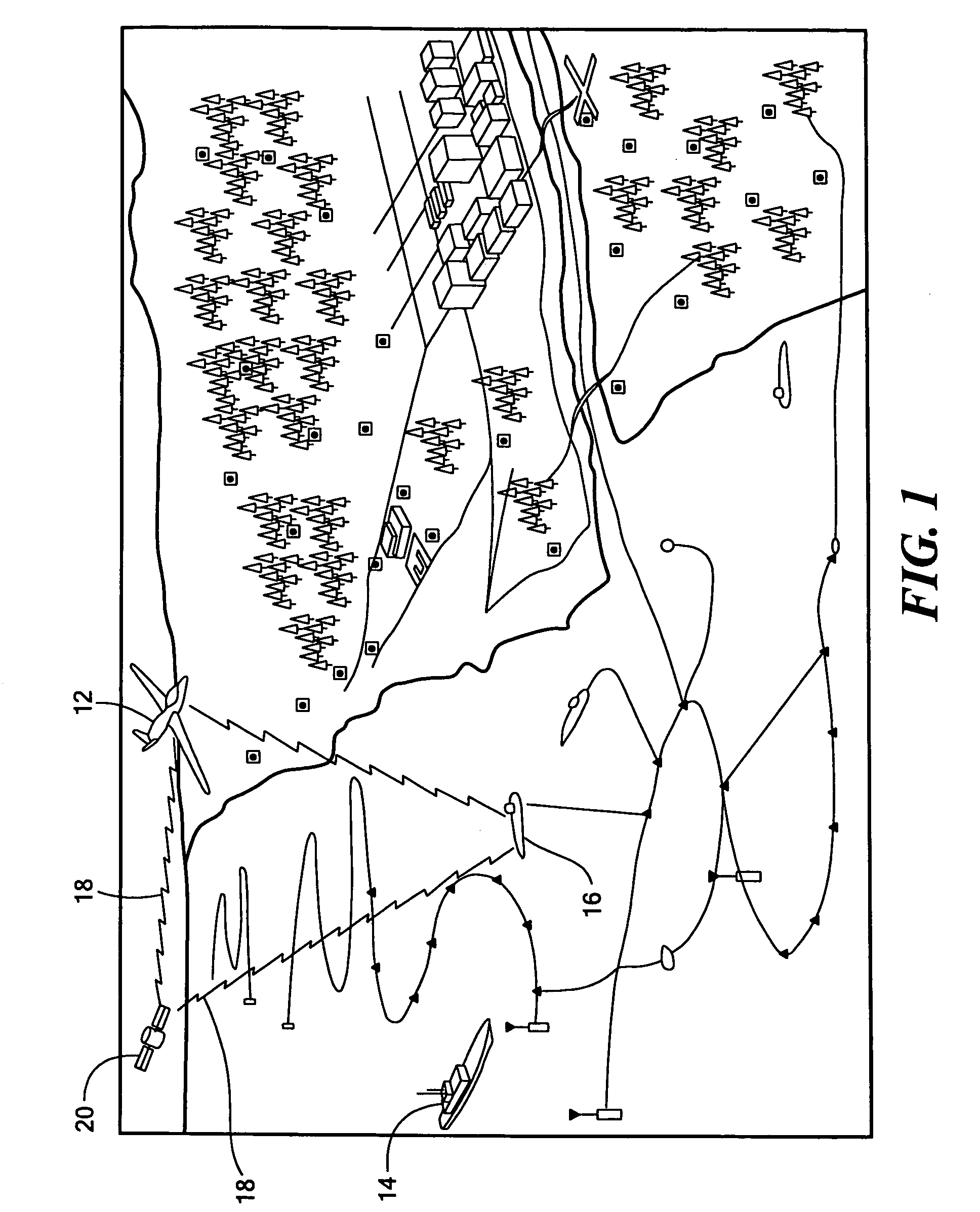
[0042]As discussed in the Background section above, in the naval littoral combat scene shown in FIG. 1, multiple forces, including Naval Aviation 12, surface Navy 14, and army or marine ground forces, work in cooperation. Underwater vessels such as submarines 16 cooperate with all of the forces. Communications such as image...


PUM


Abstract

An extendable spar buoy sea-based communication system includes a spar buoy having a retracted configuration deployable from an underwater vessel and an extended configuration after deployment, and a communication subsystem mounted to the top of the spar buoy and supported thereby.

Description

FIELD OF THE INVENTION[0001]This invention relates to an improved sea-based communication system including an extendable spar buoy sea-based communication system for providing communications to and from an underwater vessel such as a submarine.BACKGROUND OF THE INVENTION[0002]Modern warfare frequently involves multiple branches of the military working in cooperation, and high speed and high data rate communications between the acting forces during unpredictable conditions in hostile environments is frequently necessary. Time critical targets need to be neutralized quickly. The ability to communicate high-resolution images at a very high data rate is often required. To perform and execute military missions, the effectiveness of such communications often depends on, for example, a real time data link. In another example, high-resolution intelligence surveillance and reconnaissance (ISR) images distributed by the satellite global broadcast system (GBS) may be required. In many of these...

Claims


Application Information

Patent Timeline
Patent Type & Authority Patents(United States)
IPC IPC(8): B63B22/00H04B1/59
CPCB63B22/24H01Q1/04H01Q1/10H01Q1/1235H01Q1/18H01Q1/34B63B1/048B63B2007/006B63B2203/00H04L12/12B63B22/00
Inventor PUZELLA, ANGELO M.SMITH, THOMAS C.CHANG, YUEH-CHILAMONT, BRIAN D.D'AMICO, MARIOWARDLE, LEON
Owner RAYTHEON CO
Learn More