
Gerotor mechanism for a screw hydraulic machine

a screw hydraulic machine and gerotor mechanism technology, applied in the direction of machines/engines, rotary/oscillating piston pump components, liquid fuel engines, etc., to achieve the effect of reducing hydro-mechanical losses, prolonging service life, and improving energy characteristics of the gerotor mechanism

Inactive Publication Date: 2007-06-05
OBSHCHESTVO S OGRANICHENNOJ OTVETABTVENNOSTJU FA RADIUS SERVIS
View PDF12 Cites 17 Cited by
  • Summary
  • Abstract
  • Description
  • Claims
  • Application Information

AI Technical Summary

Benefits of technology

[0012]The technical settled by the claimed invention is an improvement of the energy characteristics of the gerotor mechanism in a hydraulic motor when a hydraulic power is applied thereto and when the resulting pressure difference appears in its working members, a prolonged service life and reduced hydro-mechanical losses by virtue of provision of the lateral interference in meshing, an improved tightness along the contact lines and lower contact stresses in the maximum sliding speeds zone by way of re-distribution of the in-meshing interference and optimization of said interference depending on a distance between the immediate centre of rotation (pitch point) and the profiles contact zone.
[0013]Another technical problem is an improved manufacturability and lower cost of the gerotor mechanism by way of simplification of selection of the working pairs according to their radial interference, as well as improved energy characteristics of a gerotor mechanism in conformity with the operation conditions, e.g. for hot wells by way of decreasing the lateral interference or through provision of the side clearance in conjunction with the constant radial interference.
[0022]Said ratios for the rack-type tool initial contour being obeyed and in assembling of gerotor mechanisms having different versions of profiles; a possibility for providing the in-meshing lateral interference is ensured. Thus, a reliable tightness along the contact lines is achieved when hydraulic-power fluid flows are delivered to a hydraulic motor; and a possibility to reduce the in-meshing radial interference and to assemble the working pairs without their selection is brought about. The moment of resistance forces is lowered owing to a weaker radial interference and lighter contact stresses effected on the areas farthermost from the immediate centre of rotation (from the pitch point), that is in the maximum sliding speeds zone. Conditions of sliding of the rotor's helical teeth over the stator's helical teeth are accommodated by virtue of re-distribution of the in-meshing interference towards the decrease thereof from the minimum sliding speeds zones to those of the maximum sliding speeds.
[0027]When profile of one half of each one of the teeth in the end-face section of the rotor and / or stator is implemented as the envelope of the rack-type tool initial contour generated by the curtailed cycloid equidistance; and when profile of the other half of the rotor and / or stator s tooth is implemented as the envelope of rack-type tool initial contour generated by conjugation of circular arcs: these arrangements also allow to take into account conditions of operation of the mechanism and mitigate the one-sided wear of teeth.

Problems solved by technology

Another technical problem is an improved manufacturability and lower cost of the gerotor mechanism by way of simplification of selection of the working pairs according to their radial interference, as well as improved energy characteristics of a gerotor mechanism in conformity with the operation conditions, e.g. for hot wells by way of decreasing the lateral interference or through provision of the side clearance in conjunction with the constant radial interference.

Method used


Image

  • Gerotor mechanism for a screw hydraulic machine
  • Gerotor mechanism for a screw hydraulic machine
  • Gerotor mechanism for a screw hydraulic machine

Examples


Embodiment Construction

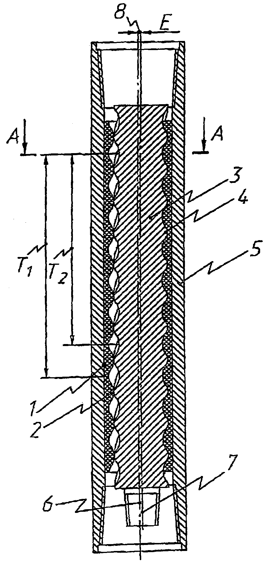
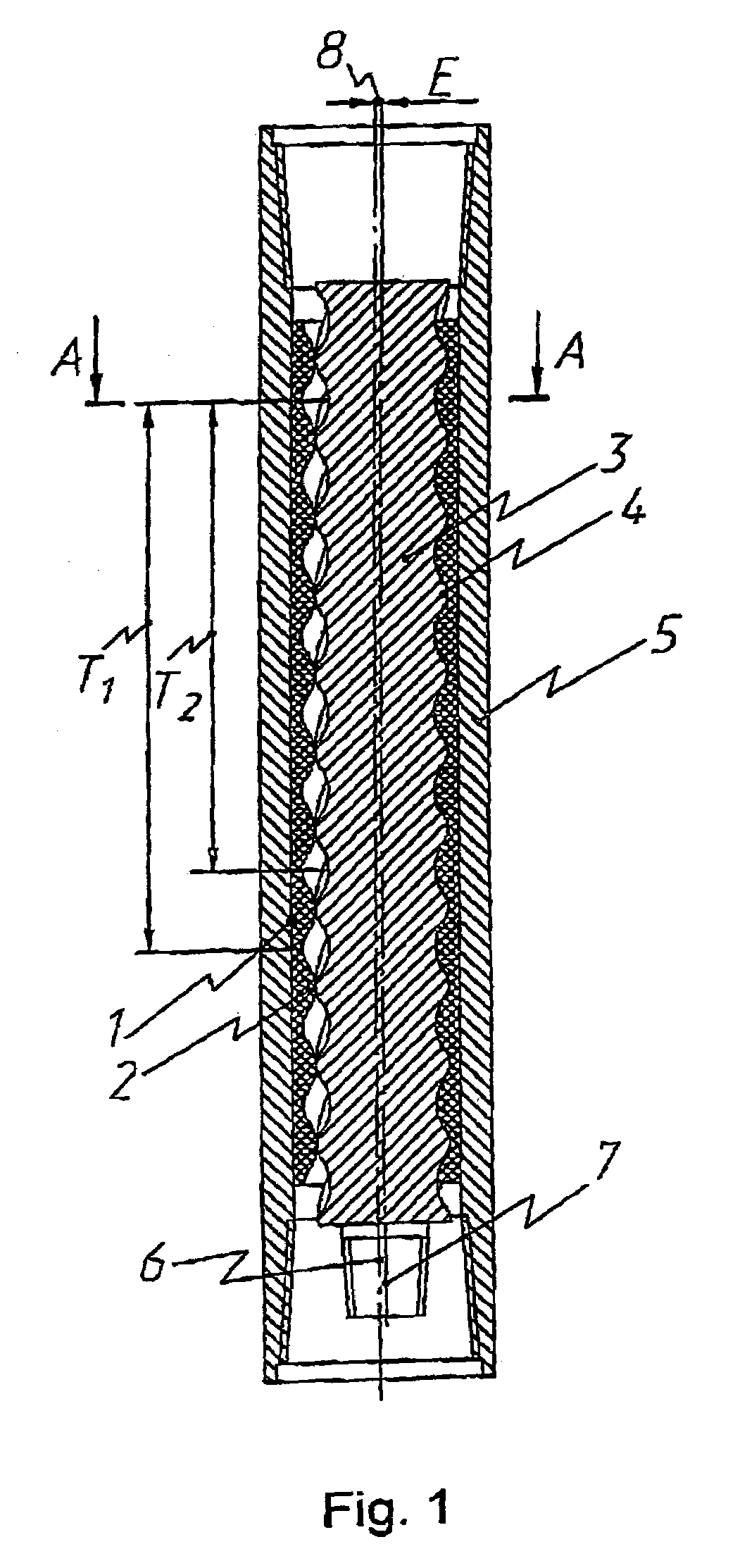
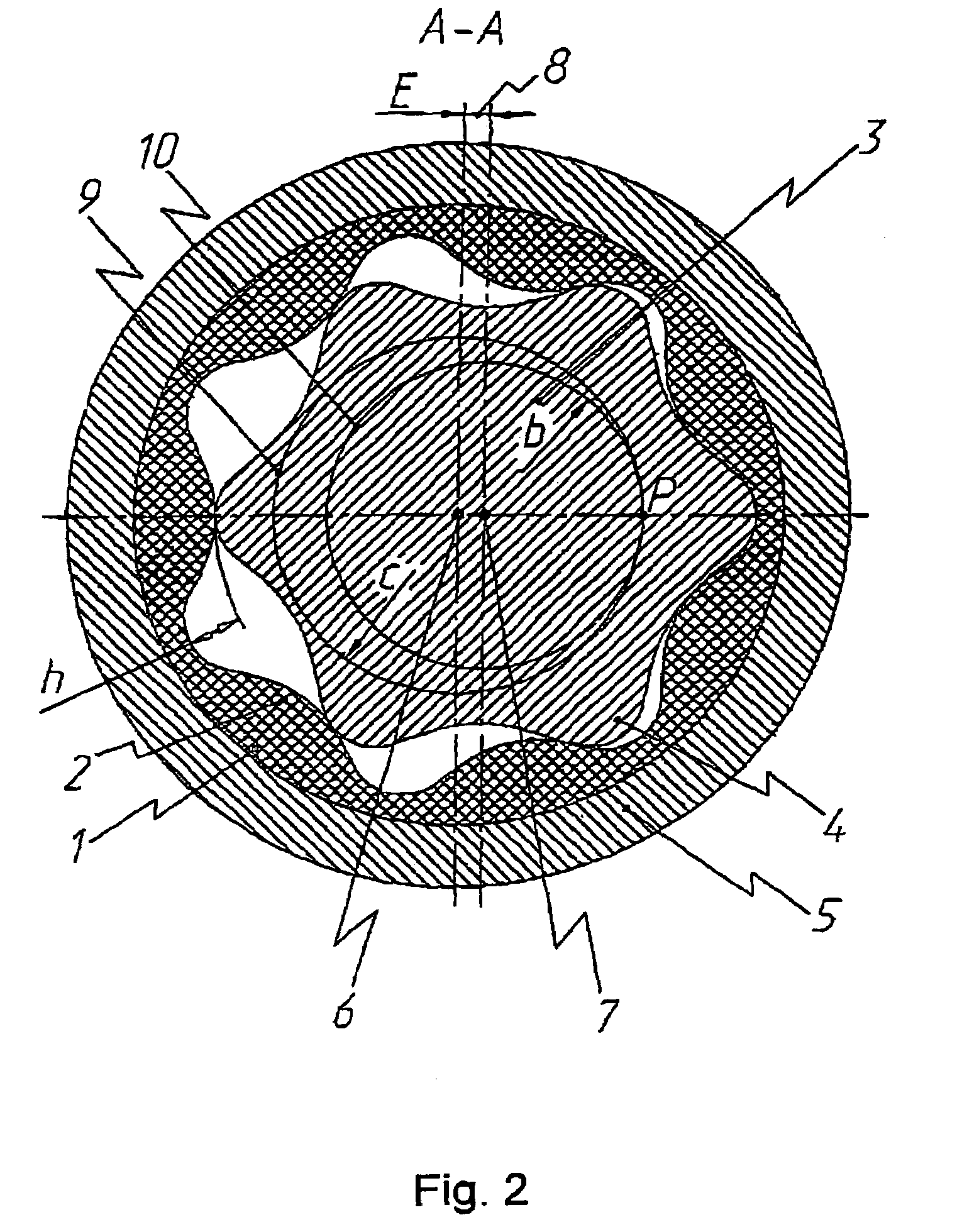
[0037]A gerotor mechanism of a screw hydraulic motor, as shown in FIGS. 1, 2, comprise stator 1 having inner helical teeth 2, rotor 3 having outer helical teeth 4 whose number by one tooth is less than those of inner helical teeth 2 of stator 1. Inner helical teeth 2 of stator 1 are made of a resilient-elastic material, for example of rubber cured onto the inner surface of body 5 of stator 1. Axis 6 of stator 1 has shifted with respect to axis 7 of rotor 3 by eccentricity 8 whose value E is equal to half of radial height of teeth 2 and 4. Working centroid 9 (the initial circumference) of stator 1 having radius c=Ez1 is in tangency to working centroid 10 (of the initial circumference) of rotor 3 having radius b=Ez2 in pitch point P, see FIG. 2. Leads of screw lines T1 and T2 of teeth 2 and 4 of, respectively, stator 1 and rotor 3, in FIG. 1, are proportional to numbers of their teeth z1 and z2.

[0038]The essential feature of the rack-type tool initial contour of the gerotor mechanism ...


PUM


Abstract

The invention relates to gerotor mechanisms for screw downhole motors used for drilling oil and gas wells, to screw pumps for producing oil and pumping fluids and to general purpose screw motors. The profiles of a rotor (3) and stator (1) are outlined in the end cross section thereof in the form of the envelop of the initial contour of a rack-type tool, which is formed by conjugation of circle arcs when said initial contour of the rack-type tool is run without sliding along corresponding tool circles. The arc radii of the circle arcs of the initial contour are calculated according to determined relations. Said invention makes it possible to improve energy characteristics, increase a life service and producibility, to reduce hydromechanical losses and costs.

Description

[0001]This application is a U.S. national phase application filed under 35 U.S.C. § 371 of international application PCT / RU2004 / 000031, filed on Feb. 3, 2004, designating the United States, which claims the benefit of Russian Application Ser. No. 2003108246, filed on Mar. 25, 2003, which are hereby incorporated by reference herein.FIELD OF THE INVENTION[0002]The invention relates to gerotor mechanisms of the screw downhole motors used for drilling the oil and gas wells, to the screw pumps employed for extracting oil and for pumping fluids, and also relates to the general-purpose screw hydraulic motors.BACKGROUND OF THE INVENTION[0003]Known is a multi-lead screw gerotor mechanism for a screw downhole motor, comprising: a stator having inner helical teeth made of a resilient-elastic material, e.g. of rubber; and a rotor having outer helical teeth, number of which outer teeth by one tooth is less than that of the stator teeth; the rotor axis being shifted with respect to the stator axi...

Claims


Application Information

Patent Timeline
Patent Type & Authority Patents(United States)
IPC IPC(8): F03C2/00F04C2/00F01C1/107F03C2/08F04C2/08F04C2/107
CPCF03C2/08F04C2/1075F04C2/084
Inventor ANDOSKIN, VLADIMIR NIKOLAEVICHASTAFIEV, SERGEI PETROVICHPUSHKAREV, MAKSIM ANATOLIEVICHGLINKIN, ALEKSEI SERGEEVICHFADEEV, MIKHAIL VALERIEVICH
Owner OBSHCHESTVO S OGRANICHENNOJ OTVETABTVENNOSTJU FA RADIUS SERVIS
Learn More