Circuit substrate manufacturing method
a technology of circuit substrates and manufacturing methods, applied in the direction of printed circuit board laminated, paper/cardboard articles, printed element electric connection formation, etc., can solve the problems of easy damage to the conveyer system, poor workability in handling copper plates, and cracks in carrying, so as to improve workability, prevent the generation of trouble in the conveyer system of carrying the base substrate, and improve the effect of workability
- Summary
- Abstract
- Description
- Claims
- Application Information
AI Technical Summary
Benefits of technology
Problems solved by technology
Method used
Image
Examples
first embodiment
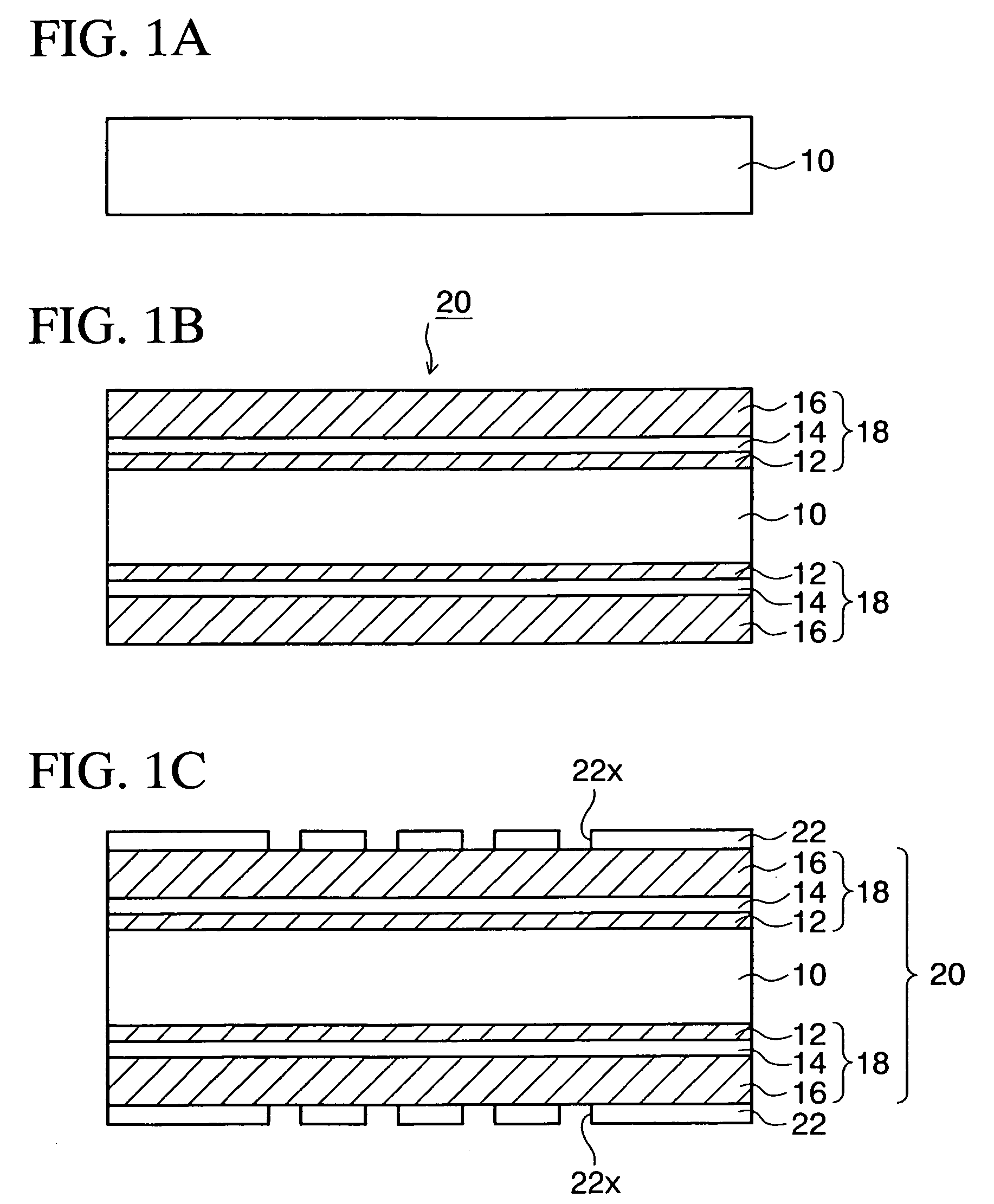
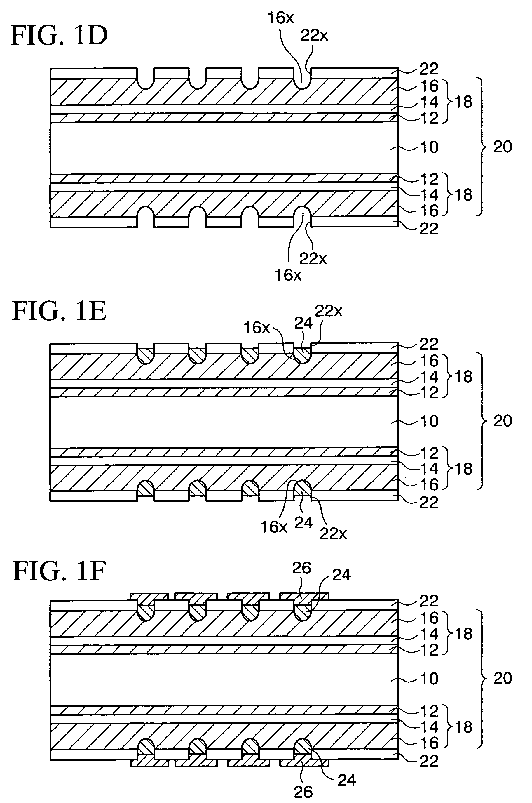
[0025]FIGS. 1A to 1L are sectional views showing a circuit substrate manufacturing method according to a first embodiment of the present invention in seriatim.
[0026]As shown in FIG. 1A, first a resin substrate 10 such as a glass epoxy resin, or the like is prepared. Then, as shown in FIG. 1B, a carrier-backed copper foil 18 having such a structure that a carrier copper foil 16 of 30 to 40 μm thickness is pasted onto a thin film copper foil 12 of 3 to 5 μm thickness via a released layer (adhesive layer) 14 is prepared. The carrier copper foil 16 is provided as a supporting member that facilitates the handling of the thin film copper foil 12.
[0027]Then, as similarly shown in FIG. 1B, an exposed surface of the thin film copper foil 12 of the carrier-backed copper foil 18 is pasted onto both surfaces of the resin substrate 10 respectively. At this time, the bump-like unevenness is provided to the exposed surface of the thin film copper foil 12 of the carrier-backed copper foil 18. There...
second embodiment
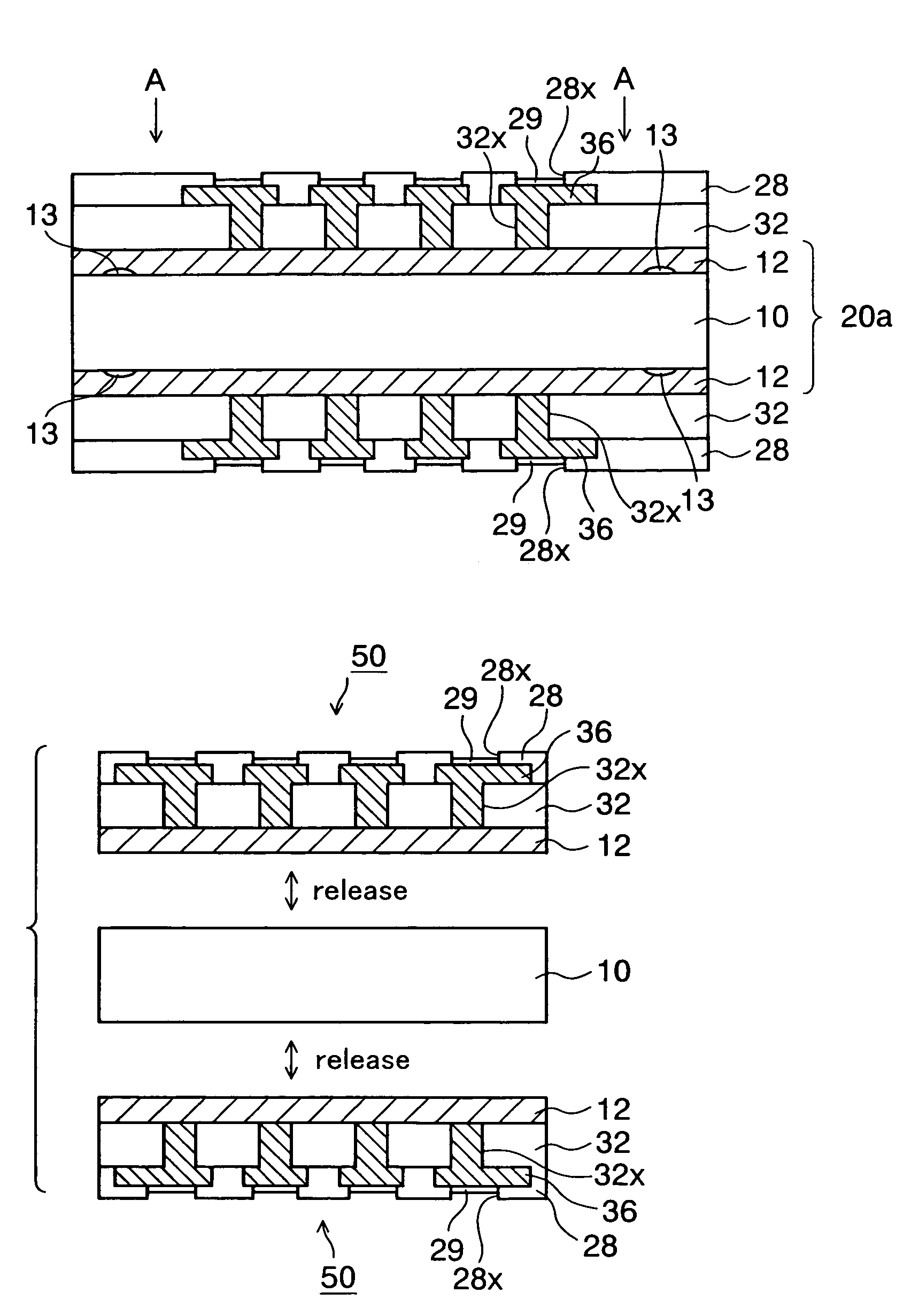
[0050]FIGS. 3A to 3I are sectional views showing a circuit substrate manufacturing method according to a second embodiment of the present invention (FIG. 3B is a plan view showing the same). A difference of the second embodiment from the first embodiment resides in that a substrate in which one copper foil layer is formed in a releasable state on the resin substrate is used as the base substrate and that the copper foil is not removed finally but the copper foil is used as the wiring pattern.
[0051]In the circuit substrate manufacturing method according to the second embodiment, as shown in FIG. 3A, first the resin substrate 10 similar to that in the first embodiment is prepared. Then, the copper foil 12 of 10 to 40 μm thickness, for example, is pasted onto both surfaces of the resin substrate 10 via an adhesive layer 13 respectively. Then, while also referring to a plan view in FIG. 3B, the adhesive layer 13 is not provided to the overall area of the resin substrate 10 but such adhe...
third embodiment
[0067]FIGS. 4A to 4F are sectional views showing a circuit substrate manufacturing method according to a third embodiment of the present invention sequentially. A difference of the third embodiment from the second embodiment resides in that a substrate in which the copper foil is pasted onto the resin substrate via the released layer is used as the base substrate.
[0068]According to the circuit substrate manufacturing method according to the third embodiment, as shown in FIG. 4A, first a base substrate 20b having such a structure that the copper foil 12 is pasted onto both surface sides of the resin substrate 10 via the released layer 14 is prepared. The released layer 14 is made of silicone, or the like, and is formed such that the released layer 14 and the copper foil 12 are easily released at the boundary between them in the later step.
[0069]Then, as shown in FIG. 4B, the insulating film 32 in which the opening portions 32x are provided is formed on the copper foil 12 on both surf...
PUM
| Property | Measurement | Unit |
|---|---|---|
| thickness | aaaaa | aaaaa |
| area | aaaaa | aaaaa |
| thickness | aaaaa | aaaaa |
Abstract
Description
Claims
Application Information
 - R&D
- Intellectual Property
- Life Sciences
- Materials
- Tech Scout
- Unparalleled Data Quality
- Higher Quality Content
- 60% Fewer Hallucinations
Browse by: Latest US Patents, China's latest patents, Technical Efficacy Thesaurus, Application Domain, Technology Topic, Popular Technical Reports.
© 2025 PatSnap. All rights reserved.Legal|Privacy policy|Modern Slavery Act Transparency Statement|Sitemap|About US| Contact US: help@patsnap.com


