
On-line dispersion compensation device for a wavelength division optical transmission system

a wavelength division optical transmission and compensation device technology, applied in the field of online dispersion compensation devices for optical transmission systems, can solve the problems of increasing cost, low threshold value of nonlinear optical effects, and higher cost of d

Inactive Publication Date: 2007-05-22
HUAWEI TECH CO LTD
View PDF9 Cites 3 Cited by
  • Summary
  • Abstract
  • Description
  • Claims
  • Application Information

AI Technical Summary

Benefits of technology

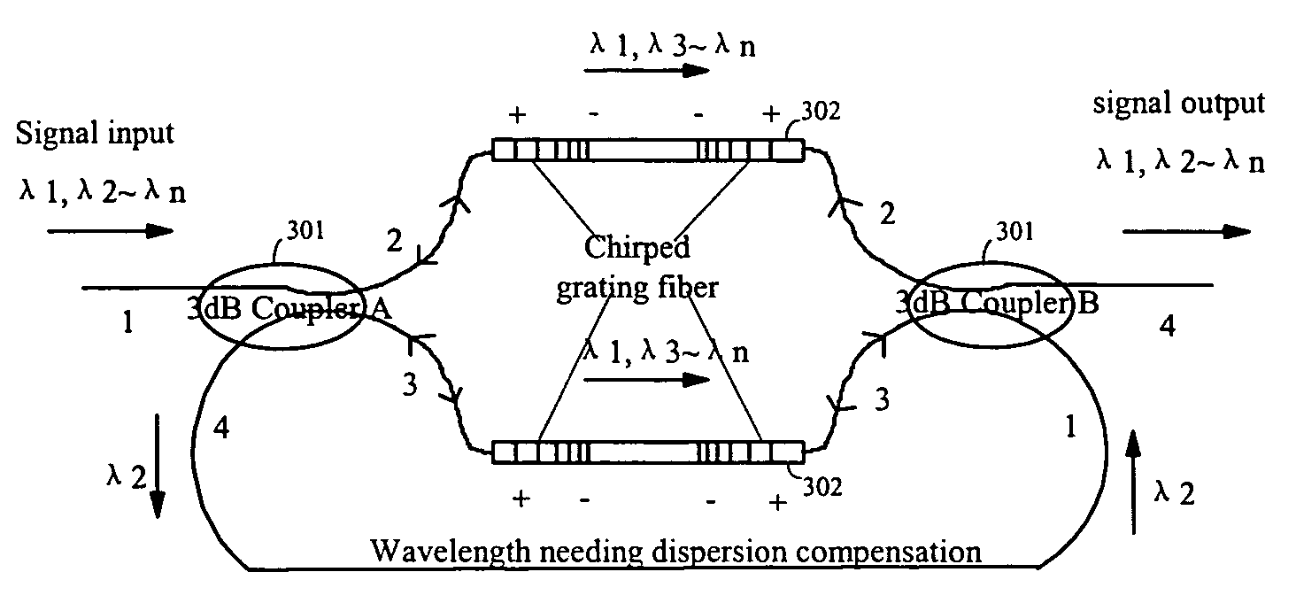
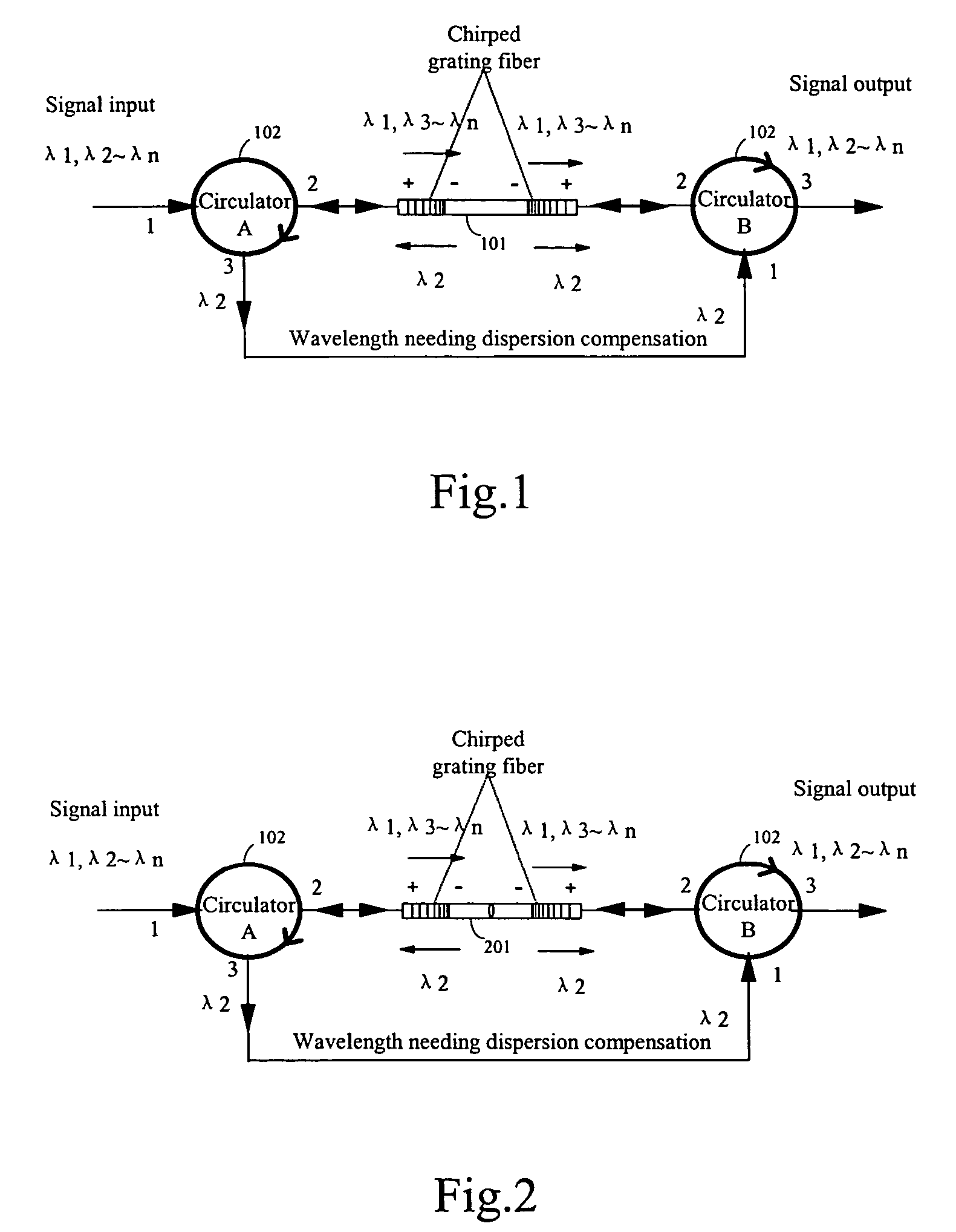
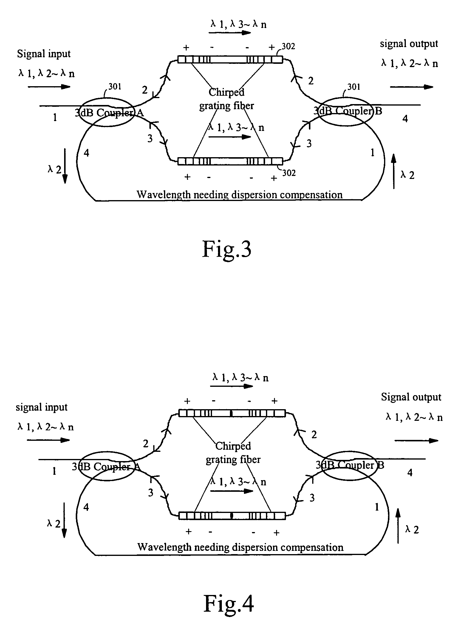
[0012]The invention applies a structure that combines a chirped grating fiber unit with two optical path selectors. The structure is suitable to on-line dispersion compensation in a DWDM system and has low insertion loss. When only a few wavelengths need to be compensated, the structure makes dispersion compensation with low cost, low insertion loss and compensating a large dispersion value, corresponding to two chirped grating fibers dispersion. The further advantage of the invention is that it can make on-line dispersion compensation with low insertion loss. For single channel or broadband compensation, the invention provides dispersion compensation without through OADM or MUX / DEMUX filtering. For an urban area network system with rare high-speed service, the invention provides a low cost solution for dispersion compensation. The structure of the device is suitable for structure design of the integrated waveguide dispersion compensation. It corresponds to combine OADM and dispersion compensation together, so multiplexing and de-multiplexing are unnecessary. Since in the waveguide integration, it is easy to integrate 3 dB couplers or circulators with waveguide gratings. Consequently, connection structure of the dispersion compensation device of the invention is suitable to waveguide integrated technology and has advantage for the future waveguide integrated manufacture.
[0013]Further areas of applicability of the present invention will become apparent from the detailed description provided hereinafter. It should be understood that the detailed description and specific examples, while indicating the preferred embodiment of the invention, are intended for purposes of illustration only and are not intended to limit the scope of the invention.

Problems solved by technology

Especially, for a 10G and higher speed single channel and broadband system, dispersion compensation is an important issue should be considered for optical transmission apparatus development.
The disadvantage of this dispersion compensation method is larger attenuation, so it is necessary to have optical amplifier to compensate optical power, and this will increase cost.
If in an urban wavelength division system, there are only a few wavelengths needs to be compensated, then using DCF will have higher cost.
Moreover, with this method, threshold-value of nonlinear optical effect is low, so input power of the fiber needs to be controlled; and there is larger polarization mode dispersion (PMD).
Disadvantages of this manner are an inserted add / drop module will increase insertion loss and cost, especially it cannot make on-line dispersion compensation for a wavelength.
Besides, a pre-chirped manner and decision and feedback manner is immature.
There is another manner of using electrical relay to make 3R regeneration of a signal, but it is too expensive.

Method used


Image

  • On-line dispersion compensation device for a wavelength division optical transmission system
  • On-line dispersion compensation device for a wavelength division optical transmission system
  • On-line dispersion compensation device for a wavelength division optical transmission system

Examples


Embodiment Construction

[0019]The following description of the preferred embodiment(s) is merely exemplary in nature and is in no way intended to limit the invention, its application, or uses.

[0020]The present invention now will be described more fully hereinafter with reference to the accompanying drawings, in which preferred embodiments of the invention are shown. This invention may, however, be embodied in many different forms and should not be construed as limited to the embodiments set forth herein; rather, these embodiments are provided so that this disclosure will be thorough and complete, and will fully convey the scope of the invention to those skilled in the art. Like numbers refer to like elements throughout.

[0021]As shown in FIG. 1, in the embodiment the on-line dispersion compensation device is consisted of two optical path selectors and a chirped grating fiber unit 101. A circulator 102 is applied as the optical path selector. The chirped grating fiber unit 101 includes two chirped grating fi...


PUM


Abstract

The invention discloses an on-line dispersion compensation device for a wavelength division optical transmission system. The device is consisted of two optical path selectors and at least one chirped grating fiber unit. The chirped grating fiber unit is consisted of two chirped grating fibers with same wavelength band and connected oppositely. In addition, the chirped grating fiber unit is serially connected between the appropriate ports of the two optical path selectors. The invention applies a structure that combines a chirped grating fiber unit with two optical path selectors. The structure is suitable to on-line dispersion compensation in a DWDM system and has low insertion loss. When only a few wavelengths need to be compensated, the structure makes dispersion compensation with low cost, low insertion loss and compensating a large dispersion value. For single channel or broadband compensation, the invention provides dispersion compensation without through OADM or MUX / DEMUX filtering. For an urban area network system with rare high-speed service, the invention provides a low cost solution for dispersion compensation, and the structure of the device is suitable for structure design of the integrated waveguide dispersion compensation.

Description

CROSS-REFERENCE TO RELATED APPLICATIONS[0001]This application is a continuation of PCT / CN02 / 00476 filed on Jul. 5, 2002. This application claims the benefit of Chinese Patent Application No. 01145243.9 filed on Dec. 23, 2001. The disclosures of the above applications are incorporated herein by reference.FIELD OF THE INVENTION[0002]The present invention relates generally to a dispersion compensation device for an optical transmission system, and more particularly to an on-line dispersion compensation device for a wavelength division high-speed optical transmission system.BACKGROUND OF THE INVENTION[0003]In a high-speed optical transmission system, dispersion is an important factor that limits the transmission distance of the system. Especially, for a 10G and higher speed single channel and broadband system, dispersion compensation is an important issue should be considered for optical transmission apparatus development. In a high-speed optical transmission system, usually there are t...

Claims


Application Information

Patent Timeline
IPC IPC(8): H04B14/02H04B10/18H04B10/2519
CPCH04B10/2519
Inventor LIU, HELIANGXIONG, QIANJIN
Owner HUAWEI TECH CO LTD
Learn More