
Surface mountable transducer system

a transducer and surface mount technology, applied in the field of sensor systems, can solve the problems of ease of integration into the complete system, increased manufacturing complexity, and increased cost, and achieve the effect of simple and efficien

Inactive Publication Date: 2007-05-22
BALLY TECHNOLOGIES +1
View PDF15 Cites 171 Cited by
  • Summary
  • Abstract
  • Description
  • Claims
  • Application Information

AI Technical Summary

Benefits of technology

The present invention relates to a sensor system comprising a carrier member, a first transducer element, a second transducer element, and an electronic device. The carrier member has a first surface holding a first group of contact elements, the first transducer element has an active member and at least one contact element that aligns with one of the first group of contact elements, and the electronic device has an integrated circuit and at least one contact element that aligns with one of the first group of contact elements. The first and second transducer elements may be Si-based. The sensor system may be used for directional sensing and may have an improved signal-to-noise ratio. The carrier member may also have a second surface holding a second group of contact elements, and the first and second groups of contact elements may be electrically connected to each other to obtain electrical contact between them. The sensor system may also have a conductive layer or a lid to protect the transducer elements and other components.

Problems solved by technology

Another issue within these component industries concerns the ease of integration into the complete system.
Consequently, the transducer element and FET system disclosed in EP 561 566 requires two (or possibly more) separate stages of production which by nature makes the manufacturing more complicated and thereby also more costly.

Method used


Image

  • Surface mountable transducer system
  • Surface mountable transducer system
  • Surface mountable transducer system

Examples


Embodiment Construction

[0044]The process used for manufacturing the different elements of the sensor system involves mainly known technologies within the field of microtechnology.

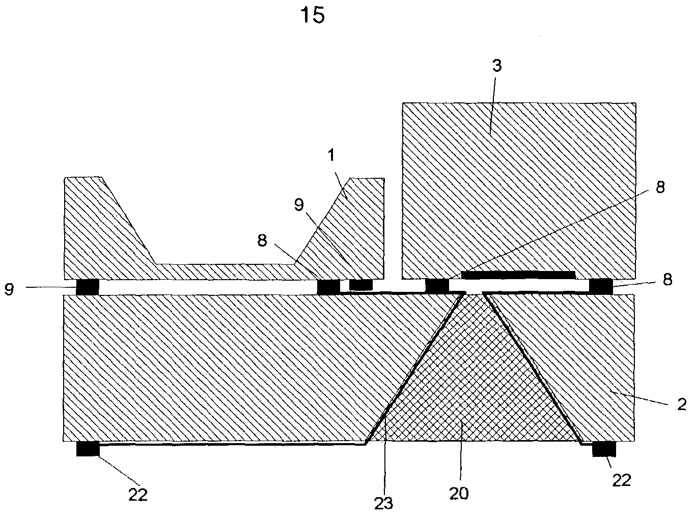
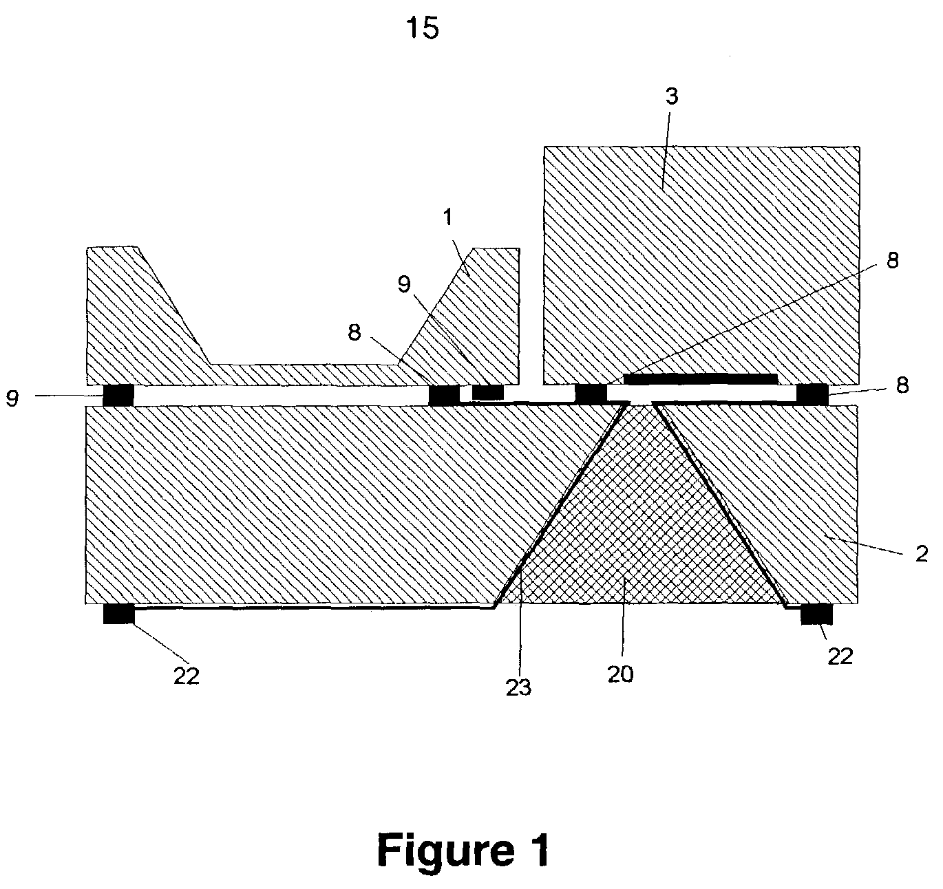
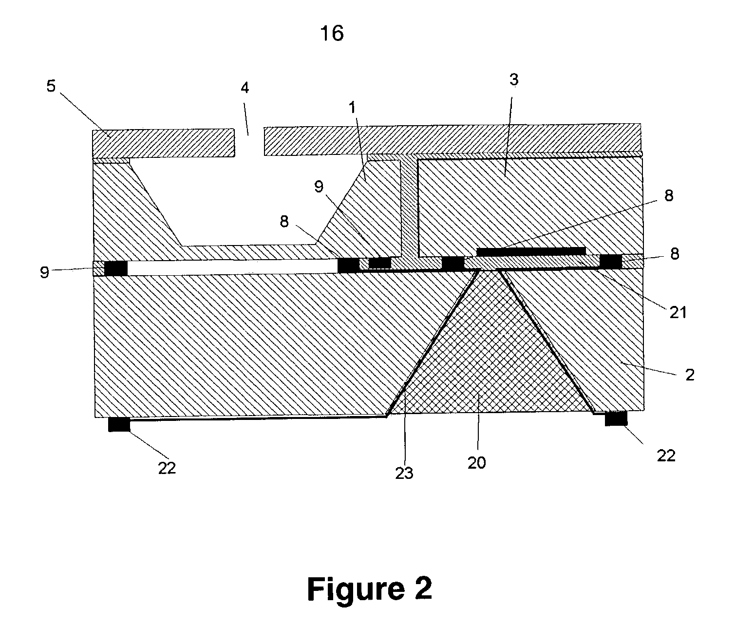
[0045]In FIG. 1 a silicon carrier substrate 2 containing one or more vertical etched feed-through holes 20 is shown. The silicon carrier substrate 2, which is bulk crystalline silicon, has solder bumps 8, 22 on a first surface and a second surface, respectively. The electrical signal is carried from the first surface to the second surface via feed-through lines 23. On the first surface, one or more transducer elements 1 are flip-chip mounted onto the silicon carrier substrate 2, connected and fixed by a first group of solder bumps 8. Also on the first surface, one or more electronic devices, such as integrated circuit chips 3, are flip-chip mounted onto the silicon carrier substrate 2, connected and fixed by a second group of solder bumps 8. The solder bump 8 material is typically Sn, SnAg, SnAu, or SnPb, but other metals could a...


PUM


Abstract

The present invention relates to a surface mountable acoustic transducer system, comprising one or more transducers, a processing circuit electrically connected to the one or more transducers, and contact points arranged on an exterior surface part of the transducer system. The contact points are adapted to establish electrical connections between the transducer system and an external substrate, the contact points further being adapted to facilitate mounting of the transducer system on the external substrate by conventional surface mounting techniques.

Description

CROSS-REFERENCE TO RELATED APPLICATIONS [0001]This is a continuation of, and claims priority under 35 U.S.C. § 120 to, U.S. application Ser. No. 09 / 570,434, filed May 12, 2000 now U.S. Pat. No. 6,522,762, which is continuation-in-part of, and further claims priority under 35 U.S.C. § 120 to U.S. application Ser. No. 09 / 391,628, filed Sep. 7, 1999 now abandoned.FIELD OF INVENTION[0002]The present invention relates to a sensor system comprising a carrier member, a transducer element and an electronic device. The present invention relates in particular to condenser microphone systems assembled using flip-chip technology. The present invention further relates to condenser microphone systems adapted for surface mounting on e.g. printed circuit boards (PCB's).BACKGROUND OF THE INVENTION[0003]In the hearing instrument and mobile communication system industry, one of the primary goals is to make components of small sizes while still maintaining good electroacoustic performance and operabili...

Claims


Application Information

Patent Timeline
Patent Type & Authority Patents(United States)
IPC IPC(8): H04R25/00H04R19/04
CPCH04R19/005H04R19/04H04R25/00
Inventor MULLENBORN, MATTHIASKUHMANN, JOCHEN F.SCHEEL, PETER
Owner BALLY TECHNOLOGIES
Learn More