Optimized path establishment method and network management system using the method

a network management system and path establishment technology, applied in the field of optimized path establishment method and network management system using the optimized path establishment method, can solve the problems of redundant network resources, manual check of every route, and frequent maintenance of routing tables, so as to reduce the time for maintenance associated with network configuration changes and reduce equipment costs

Inactive Publication Date: 2007-05-22
FUJITSU LTD
View PDF13 Cites 25 Cited by
  • Summary
  • Abstract
  • Description
  • Claims
  • Application Information

AI Technical Summary

Benefits of technology

[0013]It is an object of the present invention to provide an optimized path establishment method and a network management system using the optimized path establishment method in which route checking and network design are performed in a short time even for a large transmission network, time for maintenance associated with network configuration change can be reduced, and it is unnecessary to reserve the alternative routes so that costs for equipment can be reduced.

Problems solved by technology

There are following problems when the network management system has the routing table which is fixedly generated by the network manager beforehand.
First, since the number of network elements which form the subnetwork is very large in a large transmission network, it takes much time to check manually every route which connects endpoints when designing such a large transmission network.
Therefore, the routing table, which includes fixed data, needs maintenance frequently.
Fourth, as preparedness of a failure in a transmission network which is under operation, it is necessary to reserve alternative routes.
Therefore, there are redundant network resources.
Fifth, since network design is performed by the network manager manually, there is a high possibility that the optimum route is overlooked due to a mistake or lack of consideration in designing.
Eighth, the network manager may be forced to correct the routing table when path establishment fails.
Thus, it takes much time to complete the path establishment operation.

Method used


Image

  • Optimized path establishment method and network management system using the method
  • Optimized path establishment method and network management system using the method
  • Optimized path establishment method and network management system using the method

Examples


embodiment 1

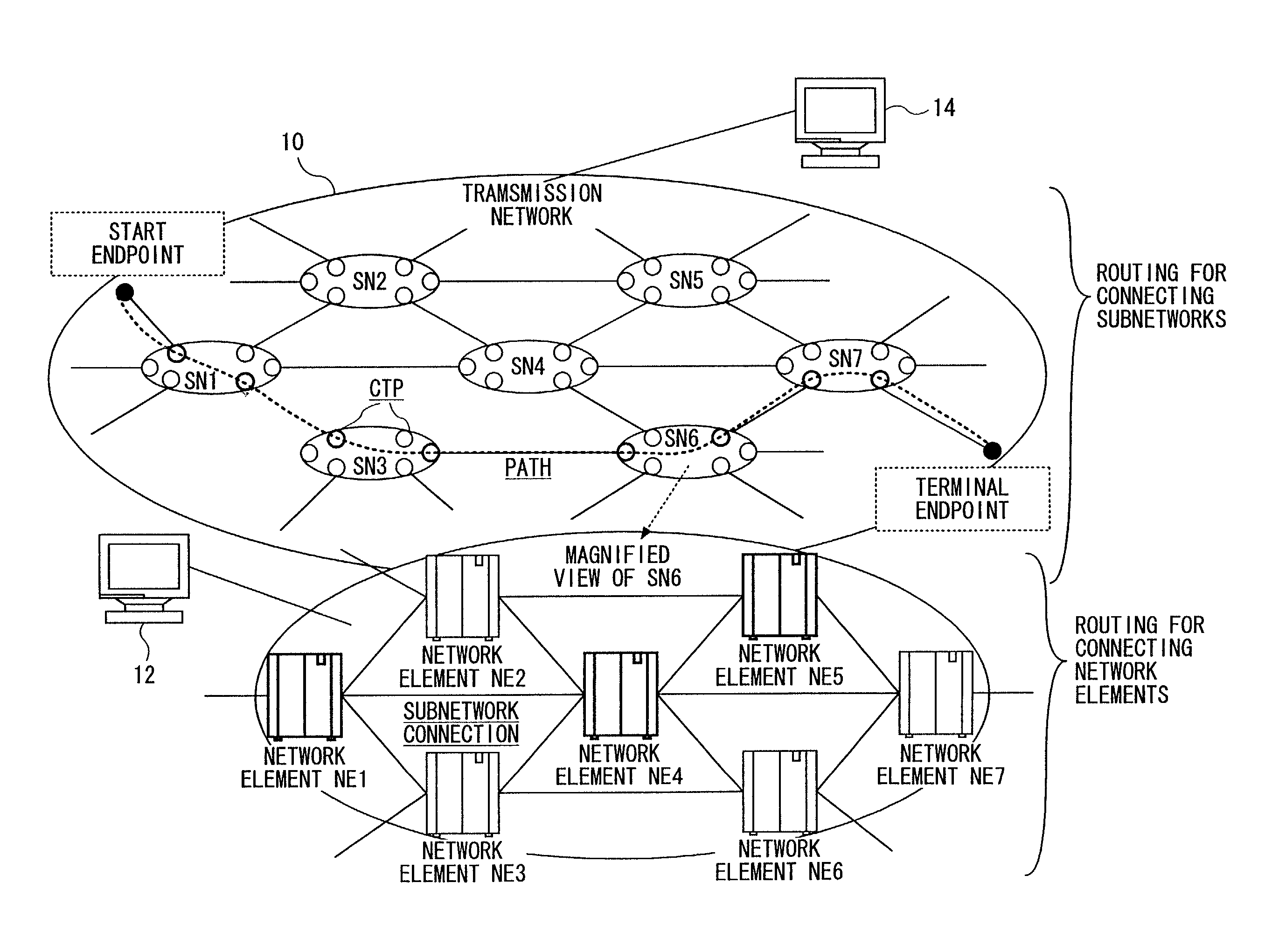
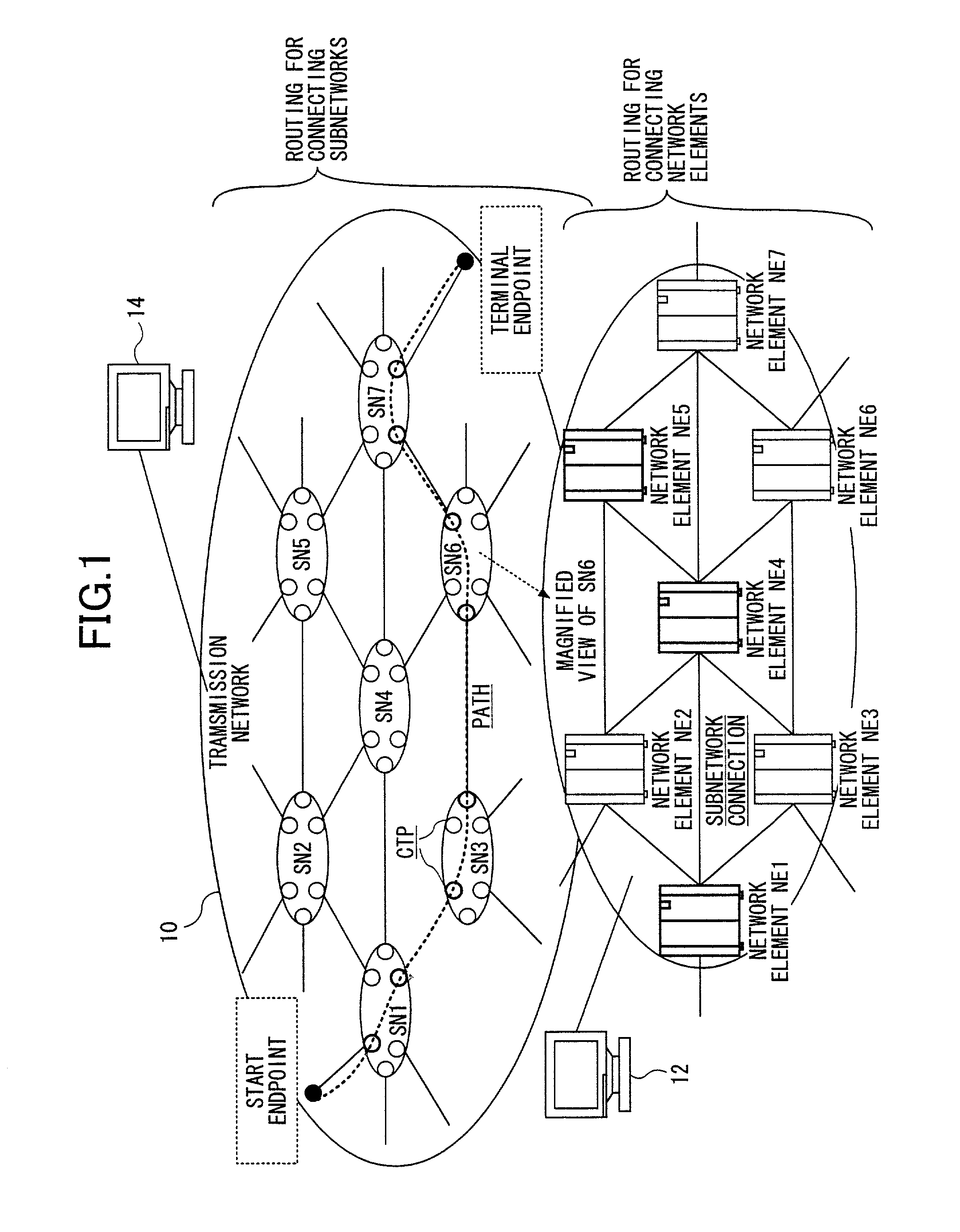
[0046]In the following, a process will be described. In this process, route selection is performed in which routes for connecting subnetworks are selected so that the dynamic routing table 30 is generated. The process is executed when the network manager specifies path establishment operation.

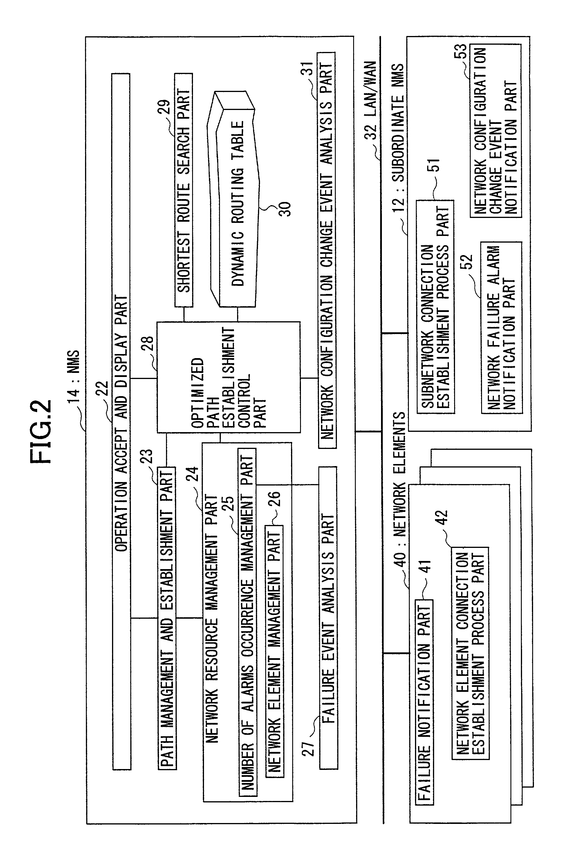
[0047](Step 1) The path management and establishment part 23 asks the network resource management part 24 about a state of implementation and availability of two endpoints (this endpoint is called TTP) which are designated in the path establishment operation by the network manager. Then, the path management and establishment part 23 provides the two endpoints (a start endpoint and a terminal endpoint) and route selection criteria to the optimized path establishment control part 28. The route selection criteria includes route selection elements which relate to route optimization and optimization coefficients each of which represents degree of optimization for a route selection element.

[0048](Ste...

embodiment 2

[0084]When subnetwork connection fails in a subnetwork while performing path establishment by using a first route candidate in the routing table, path establishment can be continued by using another route candidate. In this embodiment 2, this method will be described.

[0085](Step 11) In addition to the distance and the number of network elements and the like, the dynamic routing table 30 has an area for storing a failed connection list which includes subnetwork connections in which path establishment is failed, wherein the connections in this list are not selected next. In the failed connection list, identifiers of subnetwork connections in which path establishment is failed and identifiers of subnetwork connections which can not be used due to failure are stored for identifying subnetwork connections which should be recovered when the path establishment is failed in midstream and for determining another candidate route by which the path establishment is continued when subnetwork con...

embodiment 3

[0117]In a transmission network under operation, when a new subnetwork or a new network element is added, or, when a subnetwork or a network element is removed, an optimized route is reselected by using a route selection criteria stored in an existing path object. In this embodiment, this method will be described. As an example, a case where a subnetwork is added will be described with reference to a sequence diagram shown in FIG. 19.

[0118](Step 21) This process starts at the time when the network configuration change event analysis part 31 receives a network configuration change notification from the subordinate NMS 12 for example. In this network configuration change notification includes an added subnetwork, a physical link, CTPs which form the subnetwork and attribute information (information shown in FIG. 3) of the subnetwork connection.

[0119](Step 22) Next, the network configuration change event analysis part 31 sends a request for generating objects corresponding to the added...


PUM


Abstract

A method used for establishing an optimized path between two endpoints in a transmission network including subnetworks is provided. In the method, two endpoints and route selection elements are specified, a first route search is performed to search for route candidates each of which connects subnetworks by using data on network resources according to the route selection elements, and the route candidates is stored in a dynamic routing table. Then, at least a route candidate is selected as a selected route candidate according to the route selection elements, and a second route search is performed to search for a route connecting network elements in each subnetwork on the selected route candidate.

Description

BACKGROUND OF THE INVENTION[0001]1. Field of the Invention[0002]The present invention relates to an optimized path establishment method and a network management system using the optimized path establishment method. More particularly, the present invention relates to a method for establishing an optimized path by selecting an optimum route which connects subnetworks and to a network management system using the optimized path establishment method, wherein the subnetwork is a smallest management unit in network element groups which form a transmission network.[0003]2. Description of the Related Art[0004]Conventionally, routing technologies for avoiding various failures on paths under operation are disclosed in a transmission network management field. According to the routing technologies, a network manager determines an optimum route on the basis of minimum distance, traffic, available capacity, number of failures and the like manually, and the network manager generates a routing table...

Claims


Application Information

Patent Timeline
Patent Type & Authority Patents(United States)
IPC IPC(8): H04J1/16H04L12/28H04L12/56H04L12/701H04L12/24H04L12/715H04L12/721
CPCH04L41/0826H04L45/04H04L45/28H04L41/0816
Inventor KAWANO, SATOSHINAKAJIMA, HIDEKAZUAZUMA, YOICHIKIMURA, MITSUMAROTAKAHASHI, NOBUO
Owner FUJITSU LTD
Why Eureka
Try Eureka