
Backlight device of liquid crystal display device and method fabricating the same

a backlight device and liquid crystal display technology, applied in lighting support devices, lighting and heating apparatuses, instruments, etc., can solve the problems of low color realization ratio of backlight devices using fluorescent lamps, limited practical use of white color light, and large size of crts, so as to improve light efficiency and minimize color division area

Active Publication Date: 2007-05-22
LG DISPLAY CO LTD
View PDF6 Cites 91 Cited by
  • Summary
  • Abstract
  • Description
  • Claims
  • Application Information

AI Technical Summary

Benefits of technology

[0028]An object of the present invention is to provide to a backlight unit of an LCD device, in which a plurality of light-emitting diodes are arranged in a zigzag configuration, thereby improving light efficiency, and minimizing color division area.

Problems solved by technology

However, one problem of the CRTs are their size and weight.
However, simultaneous use of the red, green, and blue LEDs to create the white color light may have limited application for practical use.
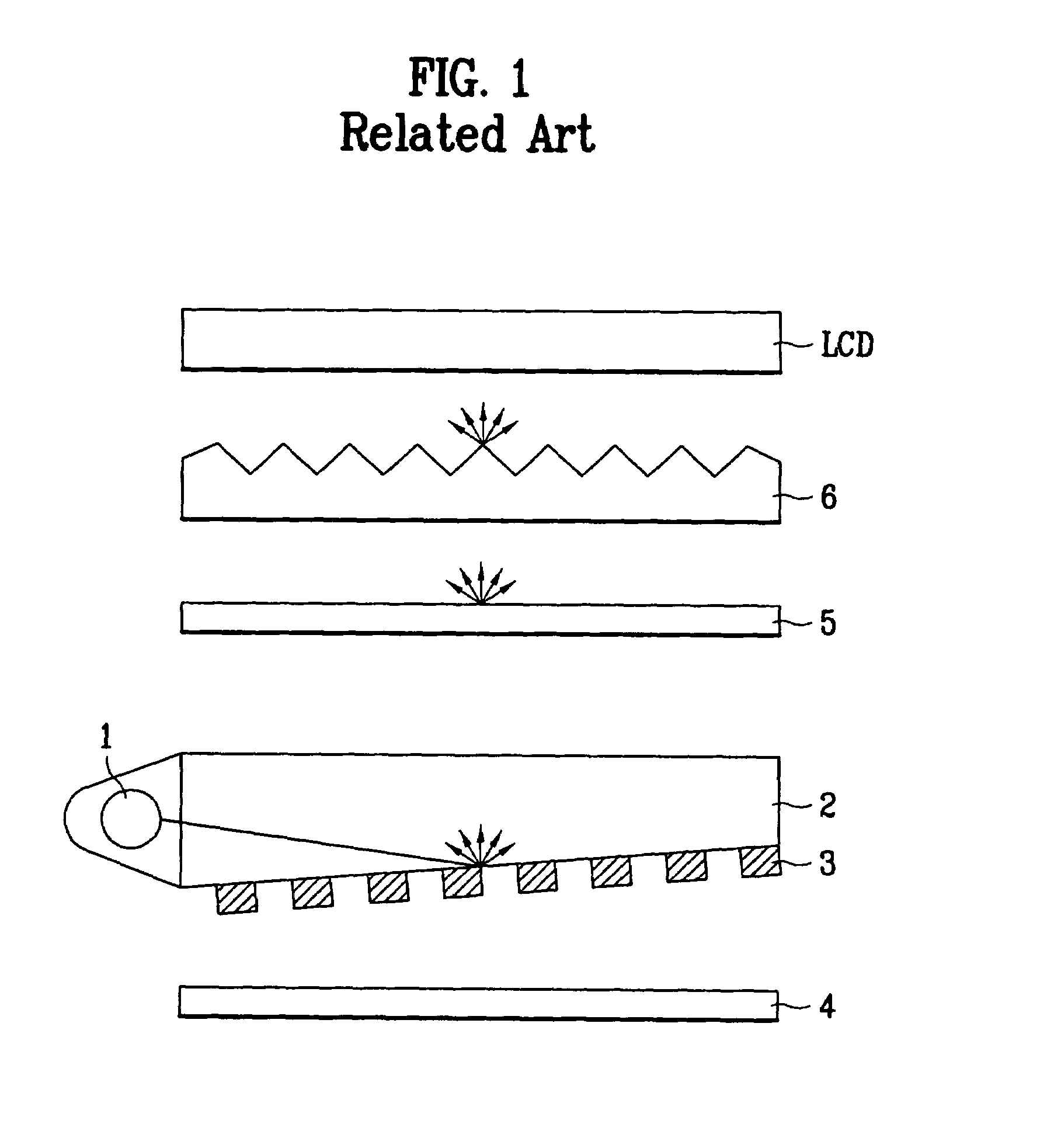
However, the backlight device using the fluorescent lamp has a low color realization ratio due to emitting characteristics of a light source.
In addition, the backlight device does not have a high luminance due to limitations, such as size and capacity of the fluorescent lamp.
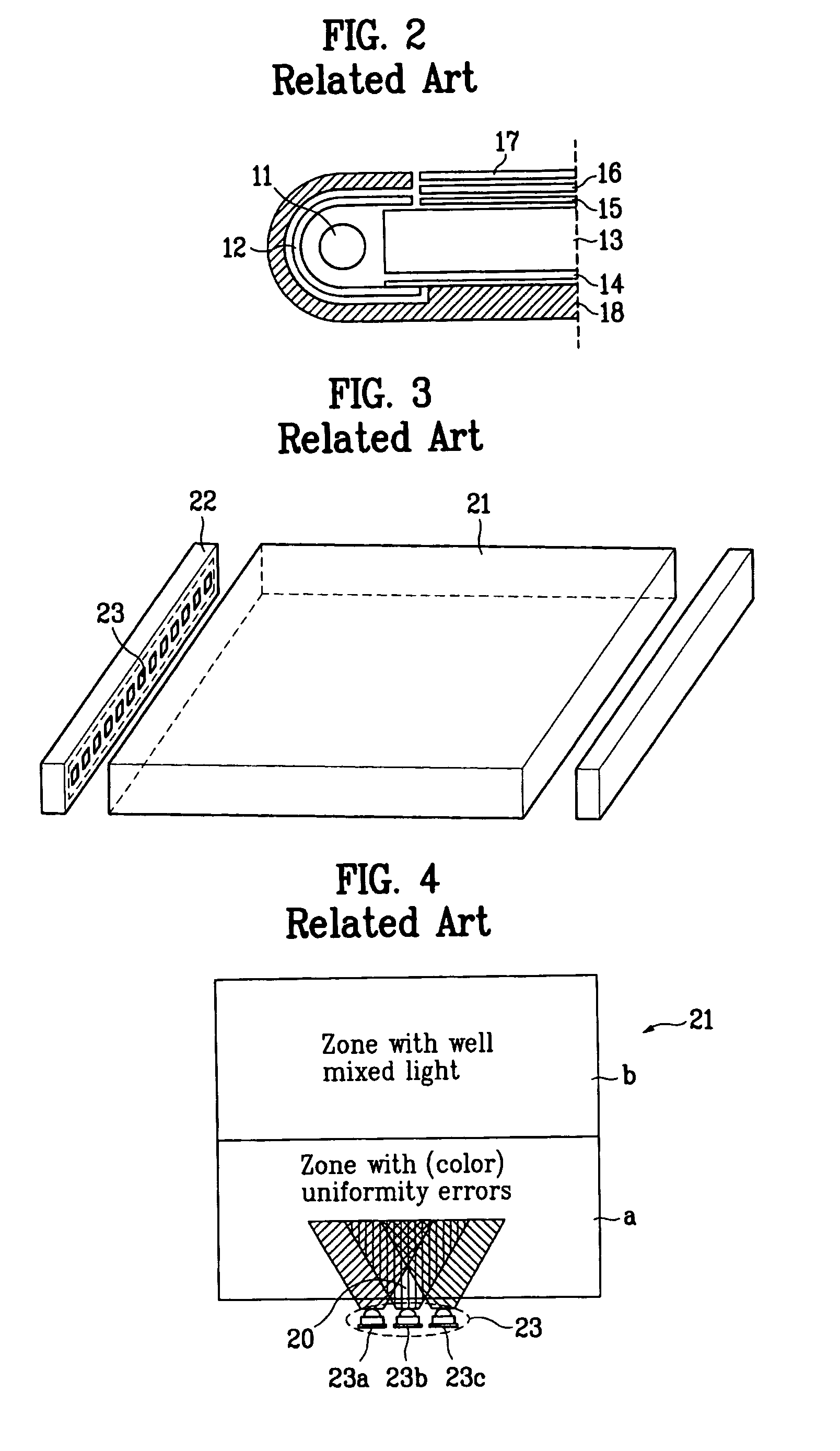
Accordingly, it is not possible to create the uniform white light within the region 20.
Furthermore, since the LED has greater reliability as compared to CRTs, the LED can be miniaturized and have a long lifetime.
However, using the backlight device in an LCD device is disadvantageous.
For example, it is difficult to uniformly mix the red, green, and blue light emitted from the red, green, and blue LED lamps in order to emit the white light having a quality color realization ratio.

Method used


Image

  • Backlight device of liquid crystal display device and method fabricating the same
  • Backlight device of liquid crystal display device and method fabricating the same
  • Backlight device of liquid crystal display device and method fabricating the same

Examples


Embodiment Construction

[0049]Reference will now be made in detail to the preferred embodiments of the present invention, examples of which are illustrated in the accompanying drawings.

[0050]FIG. 5 is a perspective view of an exemplary LCD device according to the present invention. In FIG. 5, an LCD device may include a metal shield case 31 for forming an upper frame, and a display window 32 for forming an effective screen of an LCD module. An LCD panel 33 may be formed below the shield case 31 and the display window 32, and the LCD panel 33 may include a thin film transistor (TFT) having source and drain electrodes, a gate electrode, and an amorphous silicon layer, and a color filter between two glass substrates. In addition, the LCD panel 33 may include a drain circuit substrate 34, a gate circuit substrate 35, an interface circuit substrate 36, and joiners 37, 38, and 39 for joining the circuit substrates together. The circuit substrates 34, 35, and 36 may be affixed to the shield case 31 by an insulati...


PUM


Abstract

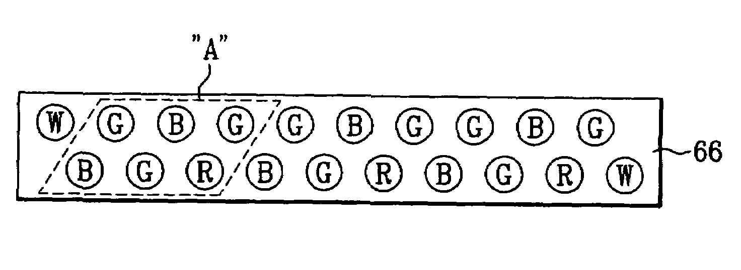
A backlight device for a liquid crystal includes a substrate, a light source including a first plurality of green light emitting diodes, a second plurality of blue light emitting diodes, and a third plurality of red light emitting diodes arranged along a first row direction on the substrate in an offset matrix-type configuration, wherein white light emitting diodes are disposed at both ends of the configuration of the green, blue, and red light emitting diodes.

Description

[0001]The present invention claims the benefit of Korean Patent Application No. P2002-58524 filed in Korea on Sep. 26, 2002, which is hereby incorporated by reference.BACKGROUND OF THE INVENTION[0002]1. Field of the Invention[0003]The present invention relates to a display device and a method of fabricating a display device, and more particularly, to a backlight device of a liquid crystal display (LCD) and a method of fabricating a backlight device of a liquid crystal display.[0004]2. Discussion of the Related Art[0005]Cathode ray tubes (CRTs) have been commonly used as monitors for televisions, measuring devices, and information terminals. However, one problem of the CRTs are their size and weight. Accordingly, display devices, such as liquid crystal display (LCD) devices that make use an electro-optics effect, plasma display panel (PDP) device that make use of a gas discharge, and electro-luminescence display (ELD) devices that make use of an electro-luminescence effect, have been...

Claims


Application Information

Patent Timeline
IPC IPC(8): F21V7/04G02F1/13357F21V8/00G02B6/00
CPCG02B6/0068G02B6/0028G02B6/0031G02B6/0086Y10S362/80G02F1/1335
Inventor AHN, IN HOKIM, JAE BURNYANG, SEUNG HOON
Owner LG DISPLAY CO LTD
Learn More