
Structure of automobile lamp

Inactive Publication Date: 2007-05-15
CHEN TO CHENG
View PDF4 Cites 6 Cited by
  • Summary
  • Abstract
  • Description
  • Claims
  • Application Information

AI Technical Summary

Benefits of technology

[0012]The object of the present invention is to provide an improved structure of an automobile lamp in which a colored mask pervious to light can be extended or retracted with the action of a mechanical means, so that the white-wavelength light of the headlight can be instantaneously changed into an orange-wavelength light to pierce the dense fog. In this way, the distance of the road illuminated by the light can be extended and thus the fog-proof effect is also achieved.
[0013]Another object of the present invention is to provide an improved structure of the automobile lamp in which one headlight can have dual functions without changing the structure and external means thereof.
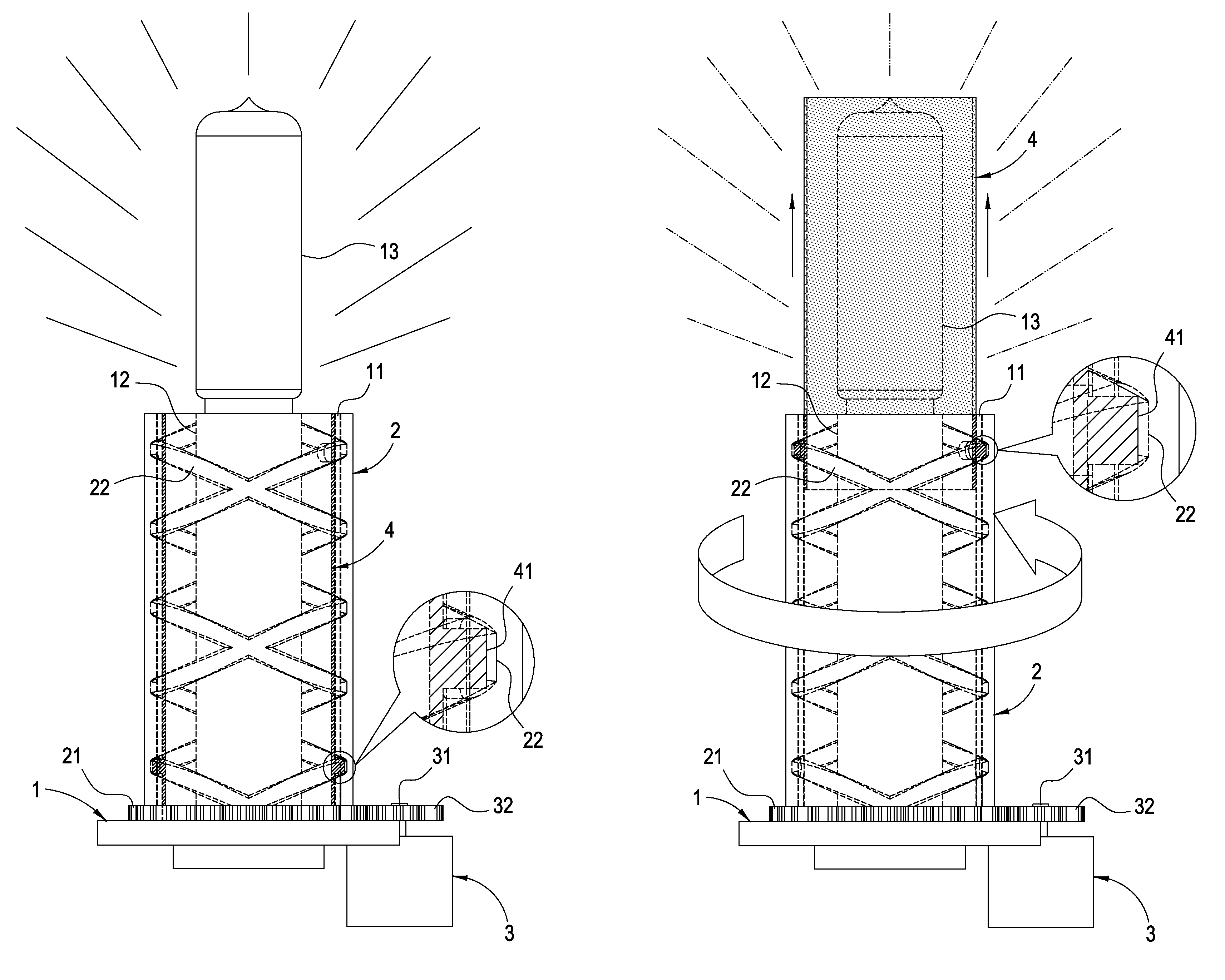
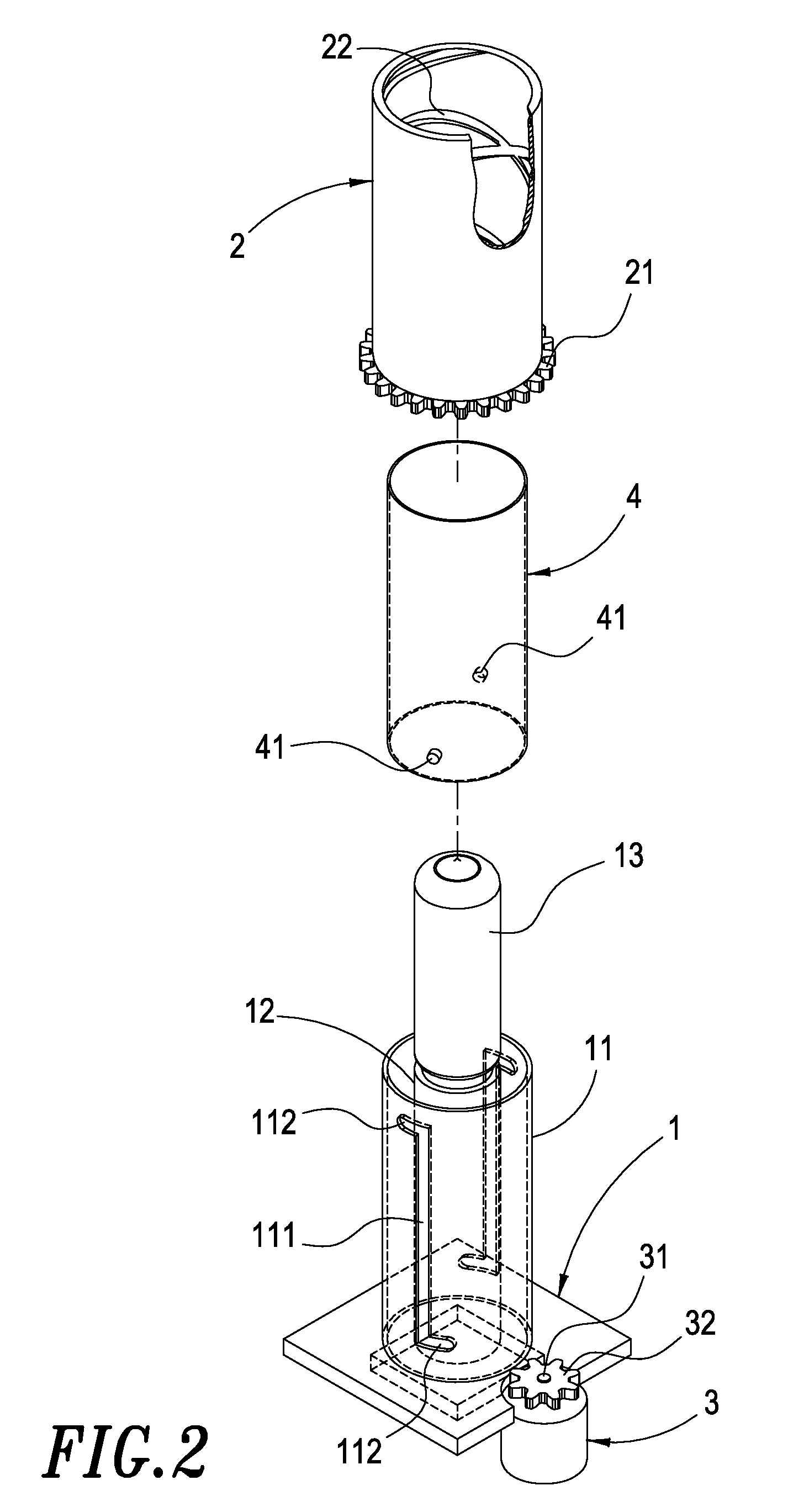
[0014]In order to achieve the above objects, the improved structure of the automobile lamp of the present invention comprises a base, a DC reduction motor, an outer pipe and an inner pipe. The base is provided with a fixing pipe to extend thereon. The fixing pipe is provided with longitudinal grooves thereon. The base is fixedly connected to a lamp seat for combining with an automobile lamp body. The lamp seat is provided in the fixing pipe. The bottom of the outer pipe is provided with a driving gear, and the inner wall of the outer pipe is provided with two staggered threads. The outer pipe is disposed to cover the outside of the fixing pipe with the driving gear at the bottom of the outer pipe near the base. The output shaft of the DC reduction motor is fixedly connected to a transmission gear. The DC reduction motor is fixed to one side of the base so as to engage the transmission gear on the output shaft of the DC reduction motor with the driving gear at the bottom of the outer pipe. The inner pipe has a certain color. A guiding rod extends from each of two opposite locations on the outer wall of the inner pipe. The inner pipe is disposed between the lamp seat and the fixing pipe with the two guiding rods penetrating through the two longitudinal grooves of the fixing pipe, and thus the inner pipe is received in the two staggered threads on the inner wall of the outer pipe. When the output shaft of the DC reduction motor rotates, it synchronously drives the outer pipe to rotate. As a result, due to the rotation of the outer pipe and the restriction of the guiding grooves of the fixing pipe, the inner pipe moves forwardly to a certain distance, thereby covering the automobile lamp body. In this way, after the white-wavelength light of the lamp body penetrates the colored inner pipe, it changes into a light having another wavelength, thereby achieving the fog-proof effect.

Problems solved by technology

However, such a structure has generated a lot of disadvantages after a long-term use.1. If the existing headlight is intended to have the functions of piercing the dense fog and increasing the illuminated distance and its illumination, it has to be additionally provided with a fog lamp so as to achieve the fog-proof effect.2. When a fog lamp is provided in the car, since the power of the bulb in the fog lamp is smaller than that of the bulb in the headlight, the illuminated distance and illumination of the light emitted by the fog lamp are also smaller than those emitted by the headlight which is changeable to a fog lamp.3. Providing an additional fog lamp makes the structure complicated and the operation troublesome.4. When two cars meets in the night, tunnel or culvert, the harsh light emitted by the headlight of the oncoming car often hurts the eyes of the driver and the driver even feels dizzy, so that a traffic accident may unfortunately happen at that time.
Therefore, the above conventional device really has some drawbacks and needs to be improved.

Method used


Image

  • Structure of automobile lamp
  • Structure of automobile lamp
  • Structure of automobile lamp

Examples


Embodiment Construction

[0021]With reference to FIGS. 2 to 4, the improved structure of the automobile lamp of the present invention mainly comprises a base 1, an outer pipe 2, a DC reduction motor 3 and an inner pipe 4.

[0022]The base 1 is provided with a fixing pipe 11 to extend thereon. The fixing pipe 11 is provided with longitudinal grooves 111 thereon. Both ends of each longitudinal groove are provided with a locking groove 112, respectively. The base 1 is provided with a lamp seat 12 for combining with an automobile lamp body 13. The lamp seat 12 is provided in the fixing pipe 11.

[0023]The bottom end of the outer pipe 2 is provided with a driving gear 21, and the inner wall of the outer pipe 2 is provided with two staggered threads 22. The outer pipe 2 is disposed to cover the outside of the fixing pipe 11 with the driving gear 21 at the bottom end of the outer pipe 2 near the base 1. The outer pipe 2 can be a metallic pipe.

[0024]The output shaft 31 of the DC reduction motor 3 is fixedly connected wi...


PUM


Abstract

An improved structure of the automobile lamp includes a base, a fixing pipe having two longitudinal grooves, and a lamp seat fixedly connected on the base inside the fixing pipe for combining with an automobile lamp body. An outer pipe is provided with a driving gear at its bottom end for engaging with a DC reduction motor and two staggered threads at its inner call. A colored inner pipe is provided between the fixing pipe and the lamp seat. Two guiding rods extend from the inner pipe and penetrate through the two longitudinal grooves of the fixing pipe to be received in the staggered threads of the outer pipe. When the output shaft of the DC reduction motor rotates, it drives the outer pipe to rotate and move the inner pipe forwardly to cover the automobile lamp body to change its light into another color.

Description

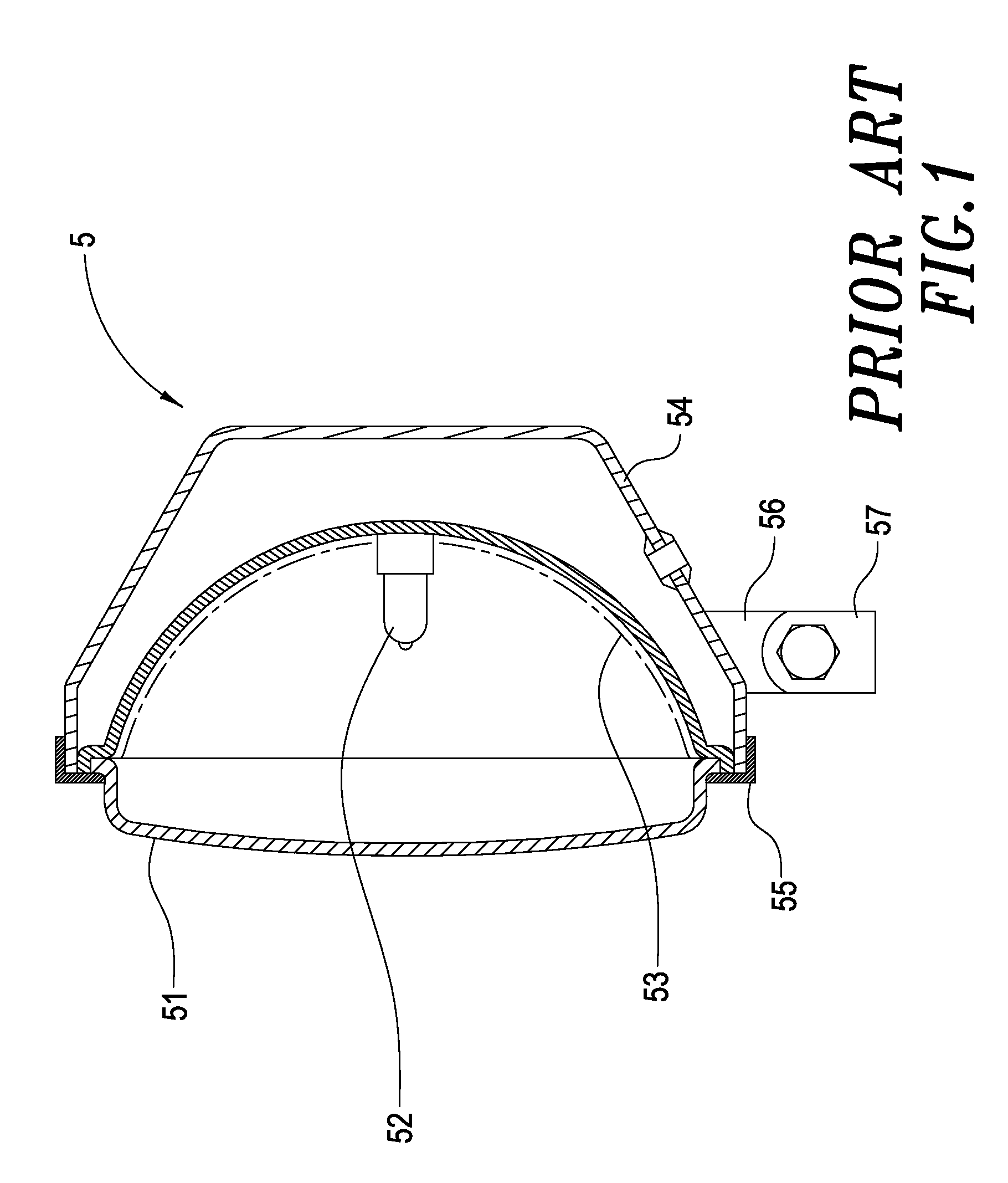
BACKGROUND OF THE INVENTION[0001]1. Field of the Invention[0002]The present invention relates to an improved structure of an automobile lamp. In particular, the present invention is characterized in that one automobile headlight has dual functions without changing the structure and external mechanism thereof.[0003]2. Description of the Prior Art[0004]FIG. 1 shows a conventional fog lamp. The fog lamp 5 is constituted of a lamp cover 51, a bulb 52, a reflective mirror 53, an outer casing 54 and an iron frame 55. By providing in the car a projecting seat 56 and a support 57 beneath the outer casing 54, when the bulb 52 emits light and the light is reflected by the reflective mirror 53, the light can pierce the glass or the transparent lamp cover 51 to the outside. With the above arrangement, a fog lamp for emitting a blazing light can be formed.[0005]Such kind of fog lamp has been used for a long time. It can provide a much clearer light for the driver when driving in a dense fog or h...

Claims


Application Information

Patent Timeline
IPC IPC(8): F21V9/10F21V9/40
CPCB60Q1/14B60Q1/20F21S48/1784F21V9/08F21S41/692
Inventor CHEN, TO-CHENG
Owner CHEN TO CHENG
Learn More