Fully differential current-feedback CMOS/bipolar operational amplifier

a technology of bipolar operation amplifier and differential current, which is applied in the direction of differential amplifiers, amplifiers with semiconductor devices/discharge tubes, dc-amplifiers with dc-coupled stages, etc., can solve the problems of less flexibility of cfb op amps and their voltage counterparts for many applications, and not as common

Inactive Publication Date: 2007-05-08
MARVELL INT LTD
View PDF7 Cites 15 Cited by
  • Summary
  • Abstract
  • Description
  • Claims
  • Application Information

AI Technical Summary

Benefits of technology

[0020]A common mode circuit is employed that compares the average of the output voltages to a set input DC voltage and outputs currents. These curren

Problems solved by technology

The low input impedance, inter alia, renders CFB op amp's less flexible than their voltage counterparts for many applications, and so they are not as common.
Moreover, CFB op amp's have been primarily expressed in bipolar components often due to the larger offset voltages of CMOS components and DC current problems in practical circuits.
Th

Method used


Image

  • Fully differential current-feedback CMOS/bipolar operational amplifier
  • Fully differential current-feedback CMOS/bipolar operational amplifier
  • Fully differential current-feedback CMOS/bipolar operational amplifier

Examples


Embodiment Construction

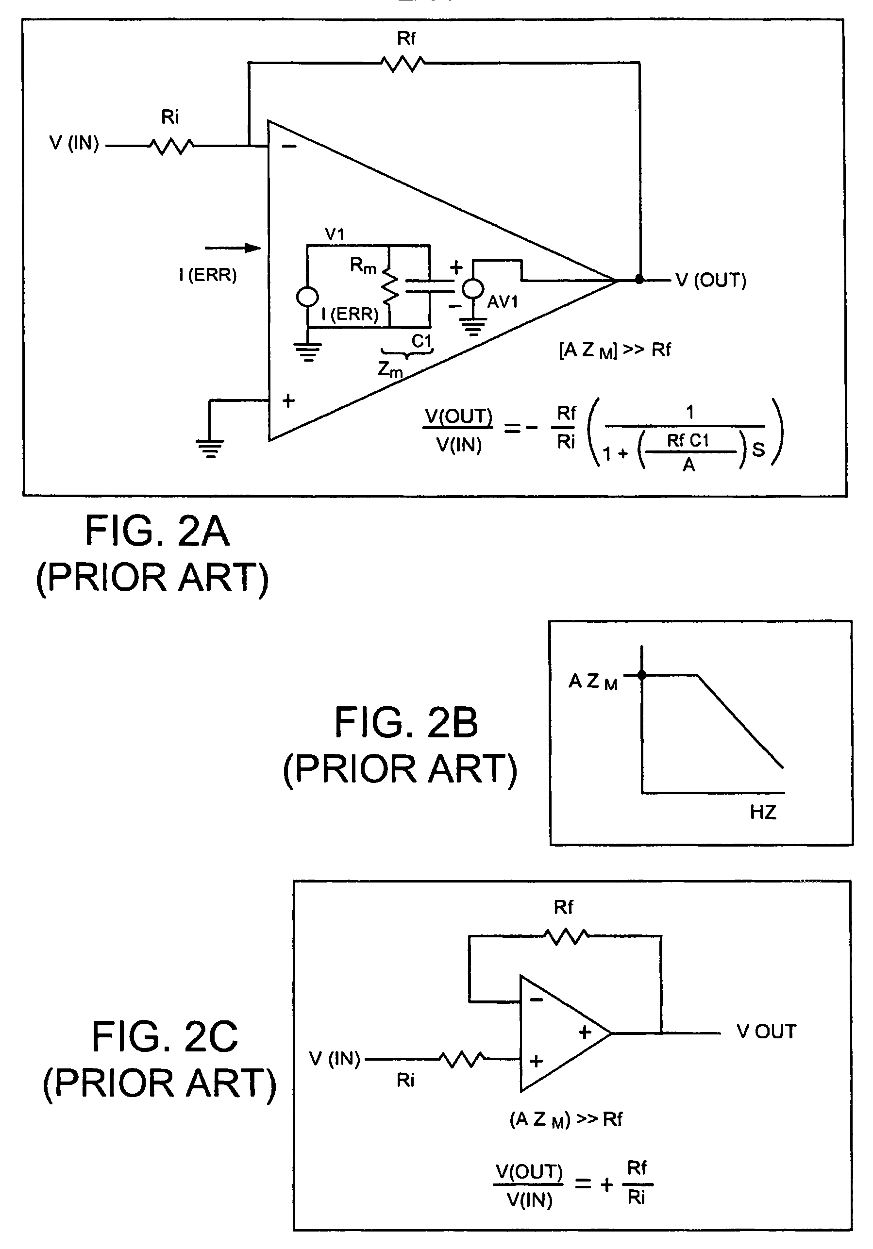
[0041]FIG. 3A is a block diagram that exists in the prior art. The circuit by inspection is a fully differential amplifier, that, when the transimpedance of the amplifier 12 is very high, acts as a fully differential current feedback operational amplifier with a differential gain, e(out) / e(in)=−(Rf / Ri).

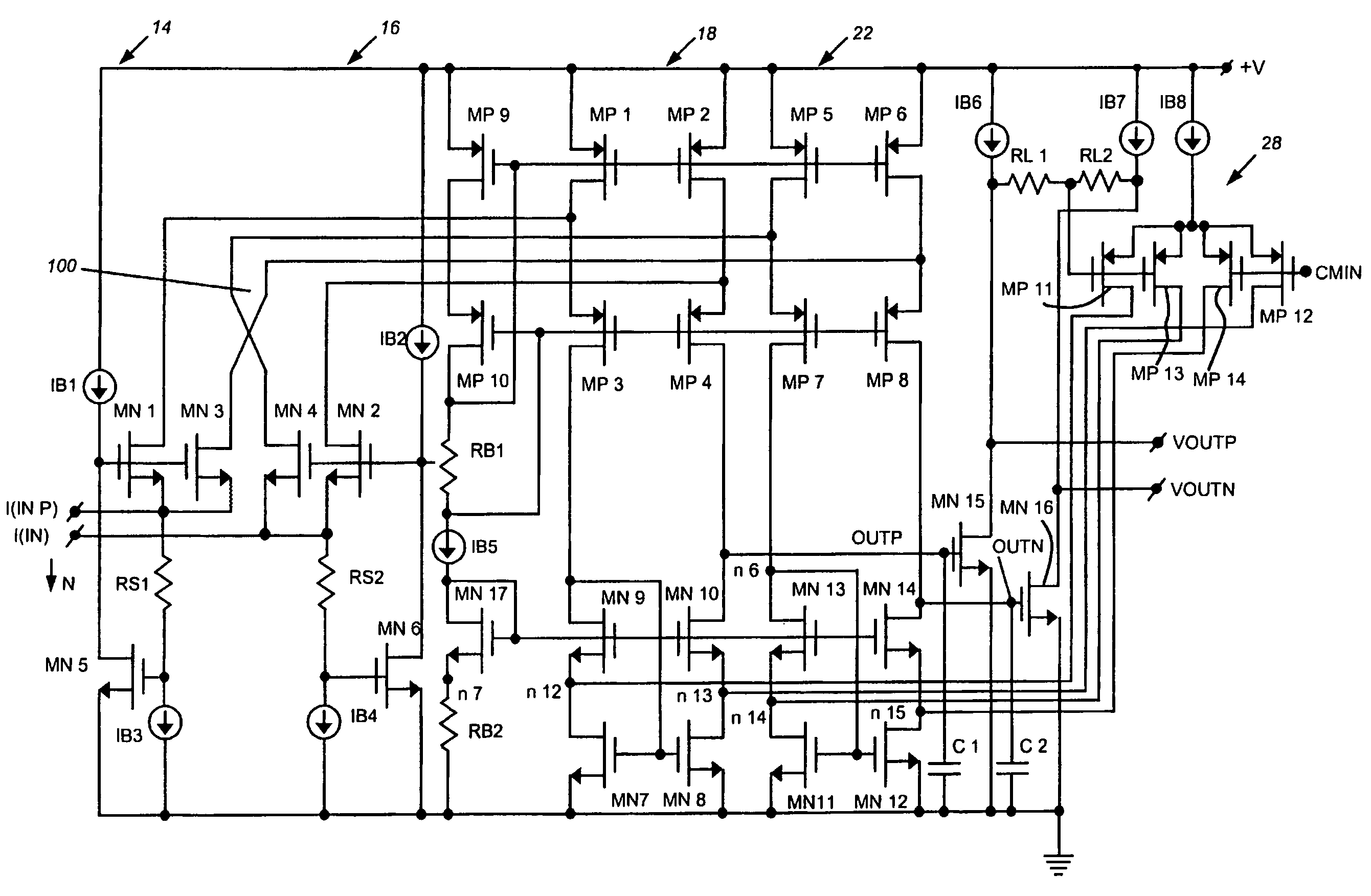
[0042]FIG. 3B is a more detailed, inventive functional block diagram of an embodiment of the inventive amplifier. There are two low impedance input circuits, circuit 14 receiving i(inp) and circuit 16 receiving i(inn). Such current designations, as known to those skilled in the art, are standard conventions for currents. Either current may actually be into (positive) or out from (negative) the amplifier inputs.

[0043]Still referring to FIG. 3B, each low input impedance input stages, 14 and 16, convert the input currents to output current pairs, i(a), i(a)′, and i(b), i(b)′, that emanate from a higher impedance. In an embodiment, i(a) and i(b) and essentially identical to i(a)′ and i(b)...


PUM


Abstract

A fully differential current feedback amplifier suitable for using in a fully differential operational amplifier circuit is disclosed. Symmetrical low input impedance input circuits receive a differential input current and provide a set of four currents that correspond to the differential input currents. These current are input to a pair of subtraction circuits that output a first voltage signal responsive to the positive difference and a second voltage signal responsive to the negative difference. In some embodiments these signals may be further amplified. A common mode circuit is provided that averages the output voltage and feeds back current in response to the subtraction circuits. In this way the average common mode output DC voltage can be set to particular voltage levels.

Description

CROSS-REFERENCE TO RELATED APPLICATIONS[0001]The present application claims the benefit of U.S. Provisional Patent Application Ser. No. 60 / 576,125, which was filed on Jun. 1, 2004, of common title and inventorship, and which provisional application is hereby incorporated herein by reference.BACKGROUND OF THE INVENTION[0002]1. Field of the Invention[0003]The present invention relates to operational amplifiers and more particularly to fully differential current feedback operational amplifiers (CFB op amp's).[0004]2. Background Information[0005]Operational amplifiers have been commonly used for many years, and a particular form of operational amplifiers, current feedback operational amplifiers, have been in use for the last two decades.[0006]Current feedback operational amplifiers have found use in high speed applications such as very fast DAC and ADC (digital to analog and analog to digital converters) and high performance video and audio applications, and the like. CFB op amp's have ...

Claims


Application Information

Patent Timeline
IPC IPC(8): H03F3/45
CPCH03F1/34H03F3/45183H03F3/45475H03F3/45632H03F2200/513H03F2203/45366H03F2203/45431
Inventor DASGUPTA, UDAY
Owner MARVELL INT LTD
Why Eureka
Try Eureka