
Motor drive circuit and motor drive method that can positively perform a brake operation

a technology of motor drive circuit and brake operation, which is applied in the direction of motor/generator/converter stopper, pulse technique, dynamo-electric converter control, etc., can solve the problems of malfunction and possible malfunction of the drive circuit operation

Inactive Publication Date: 2007-05-08
MITSUMI ELECTRIC CO LTD
View PDF18 Cites 4 Cited by
  • Summary
  • Abstract
  • Description
  • Claims
  • Application Information

AI Technical Summary

Benefits of technology

[0013]A general object of the present invention is to provide an improved and useful motor drive circuit and motor drive method in which one or more of the above-mentioned problems are eliminated.
[0014]A more specific object of the present invention is to provide a motor drive circuit and a motor drive method that can positively perform a brake operation.
[0024]According to the present invention, among a pair of transistors, one of the transistors is turned OFF and the other of the transistors is turned ON in accordance with a brake operation instruction signal, and the other of the transistors is forced to be turned OFF. Thus, it is possible to turn OFF the transistor at high speed. Accordingly, it is possible to reduce the time interval during which the pair of transistors are simultaneously ON. Thus, since it is thus possible to reduce the time interval during which a shoot-through current flows through the pair of transistors, it is possible to positively perform a brake operation and the like.

Problems solved by technology

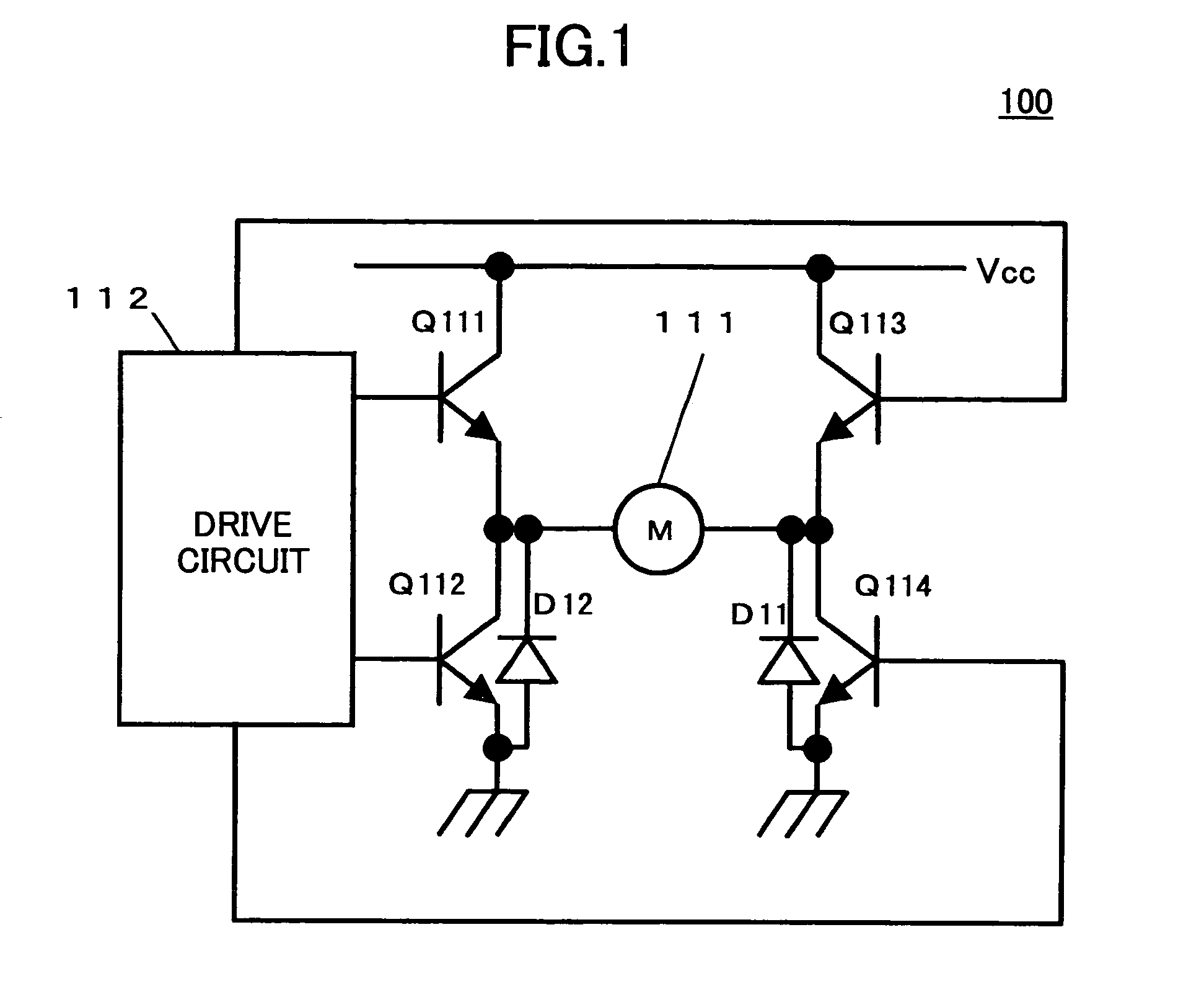
Thus, when a counter electromotive force is applied to a motor drive circuit by a motor, there is a possibility of a malfunction.
When the time interval during which the shoot-through current flows through the output transistors Q111 and Q112 is long, there is a problem in that a malfunction occurs in the operation of the drive circuit 112, for example.

Method used


Image

  • Motor drive circuit and motor drive method that can positively perform a brake operation
  • Motor drive circuit and motor drive method that can positively perform a brake operation
  • Motor drive circuit and motor drive method that can positively perform a brake operation

Examples


Embodiment Construction

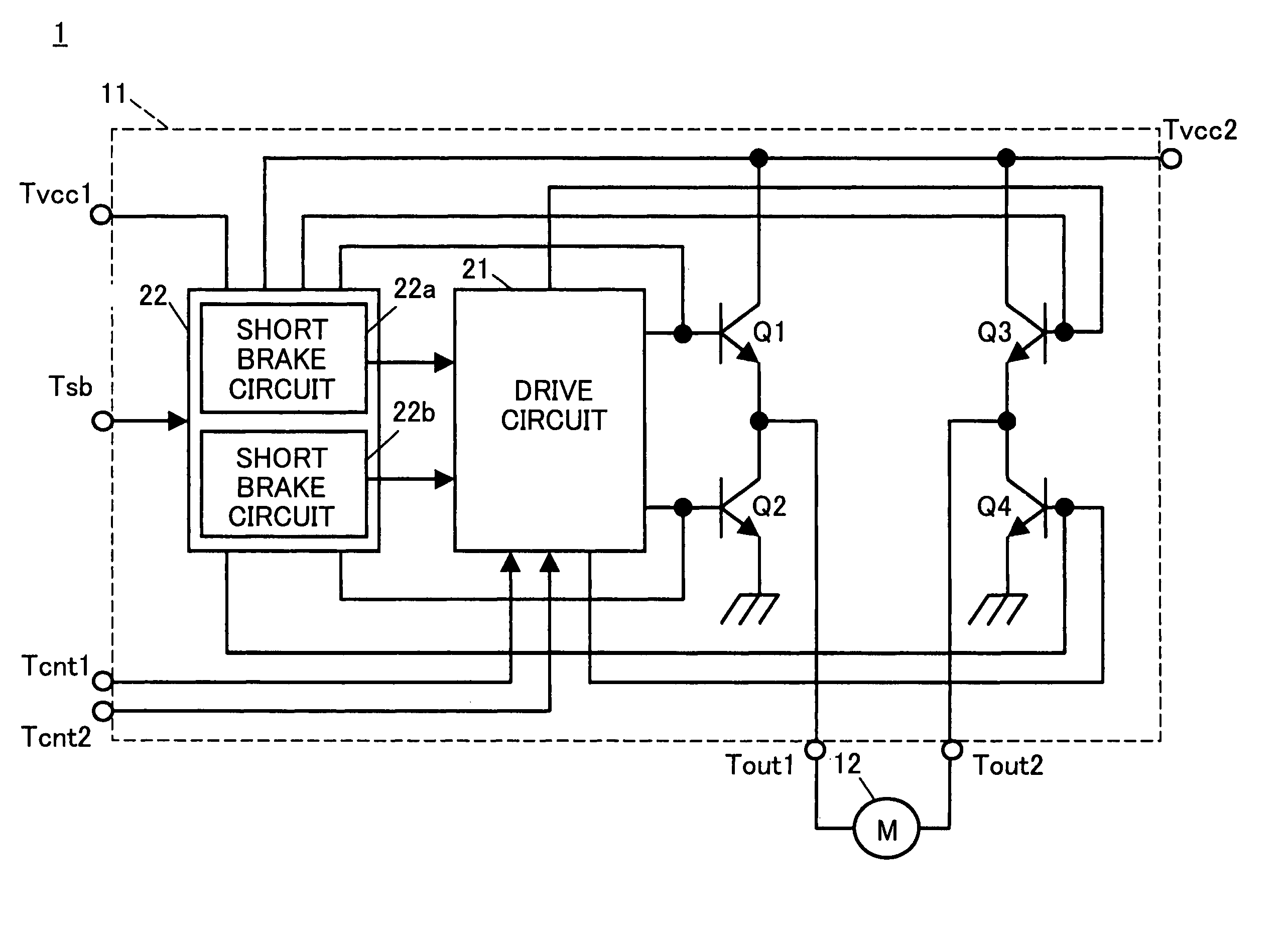
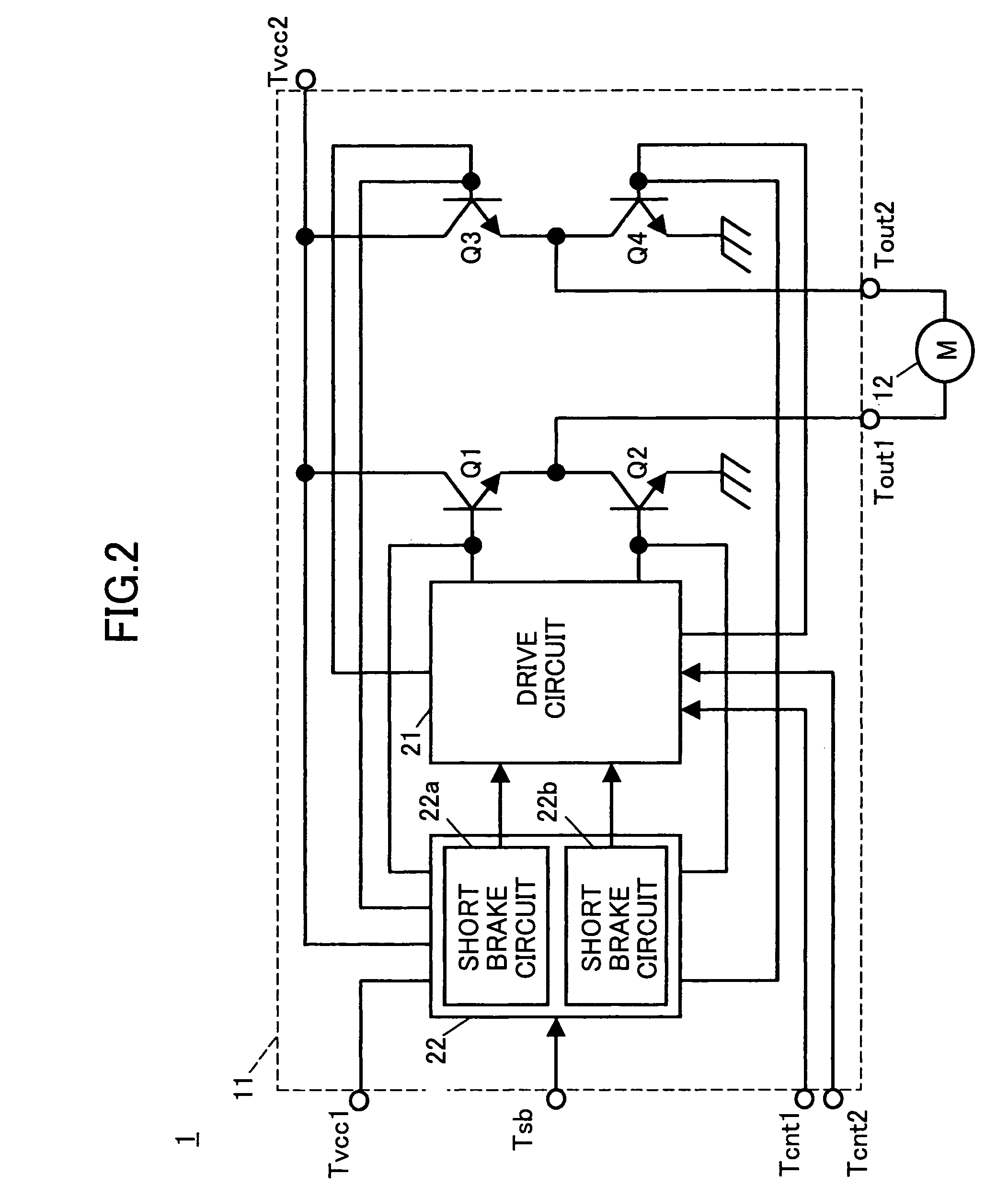
[0032]FIG. 2 is a system block diagram of a motor drive system 1 according to one embodiment of the present invention.

[0033]The motor drive system 1 of this embodiment is a system for driving a direct current motor 12 and includes a motor driving IC 11 and the direct current motor 12.

[0034]The motor driving IC 11 includes a drive circuit 21, a short brake circuit 22, and output transistors Q1 through Q4. The motor driving IC 11 also includes, as outside terminals, at least power supply terminals Tvcc1 and Tvcc2, output terminals Tout1 and Tout2, control terminals Tcnt1 and Tcnt2, and a short brake terminal Tsb.

[0035]A power supply voltage Vcc1 is applied to the power supply terminal Tvcc1, and a power supply voltage Vcc2 is applied to the power supply terminal Tvcc2. The direct current motor 12 is connected between the output terminals Tout1 and Tout2. A rotation control signal is supplied to the control terminal Tcnt1 from a microcomputer, for example. A rotation direction control ...


PUM


Abstract

A motor drive circuit includes a first transistor. The collector of a second transistor is connected to the emitter of the first transistor in series. A motor is connected to a connection point between the first and second transistors. A first brake control circuit turns off the first transistor and turns on the second transistor in accordance with a brake operation instruction signal. A second brake control circuit forces the first transistor to be turned OFF in accordance with the brake operation instruction signal independently from the first brake control circuit.

Description

BACKGROUND OF THE INVENTION[0001]1. Field of the Invention[0002]The present invention relates to motor drive circuits and motor drive methods, and more particularly, to a motor drive circuit having a short brake function and a motor drive method capable of performing a short brake operation.[0003]2. Description of the Related Art[0004]Motor drive circuits are circuits that supply a drive current to a motor for rotating the motor. In such a motor drive circuit, when the supply of the drive current to the motor is stopped in a state where the drive current is supplied to the motor and the motor is being rotated, the motor tries to continue rotating itself by inertia. When the motor is rotated by inertia, a counter electromotive force is generated in the motor in accordance with the rotation. The counter electromotive force generated in the motor is applied to the motor drive circuit. Accordingly, the longer the time interval of rotation of the motor is and the faster the rotation is, ...

Claims


Application Information

Patent Timeline
IPC IPC(8): H02K7/00H02P3/00H02P3/12H02P7/29H03K17/04H03K17/16H03K17/60
CPCH02P3/12
Inventor USUI, KAORUOOHARA, TOMOMITSU
Owner MITSUMI ELECTRIC CO LTD
Learn More