
Handpiece for dental or surgical use

a handpiece and surgical technology, applied in the field of handpieces for dental or surgical use, can solve the problems of reducing the service life of the handpiece, increasing vibration, and relatively high weight of the relative strength of the tightening spring, and reducing the axial stress. , to achieve the effect of reducing the axial stress and simplifying the bearing arrangemen

Inactive Publication Date: 2007-05-08
BIEN AIR HLDG SA
View PDF7 Cites 6 Cited by
  • Summary
  • Abstract
  • Description
  • Claims
  • Application Information

AI Technical Summary

Benefits of technology

[0007]The present invention aims to avoid the above-mentioned disadvantages of the prior art on the basis of an arrangement, which ensures a strong grip at the level of the gripping jaws of the clamp, while restricting the axial forces affecting the tightening and release mechanisms. An additional aim of the invention is to simplify the layout of the bearing arrangements of the handpiece, in particular by reducing the axial stresses on at least one of them.
[0009]Thus, by the action of the lever the gripping force of each gripping jaw is more than double the centripetal force applied to the supporting surface by the tightening mechanism, and in practice the lever arm ratio can easily increase to ten or more, since the tightening movement at the level of the gripping jaws can be very small.
[0010]The tightening mechanism can have a slider, which is mounted in the hollow shaft and is provided with a concave conical surface in the area of the clamp and is biased axially by a spring, which presses its conical surface against said supporting surfaces to keep the clamp tightened. If the inclination of the supporting surfaces in relation to the axis is low, the effect of the force of the spring on each lever of the clamp is further multiplied.
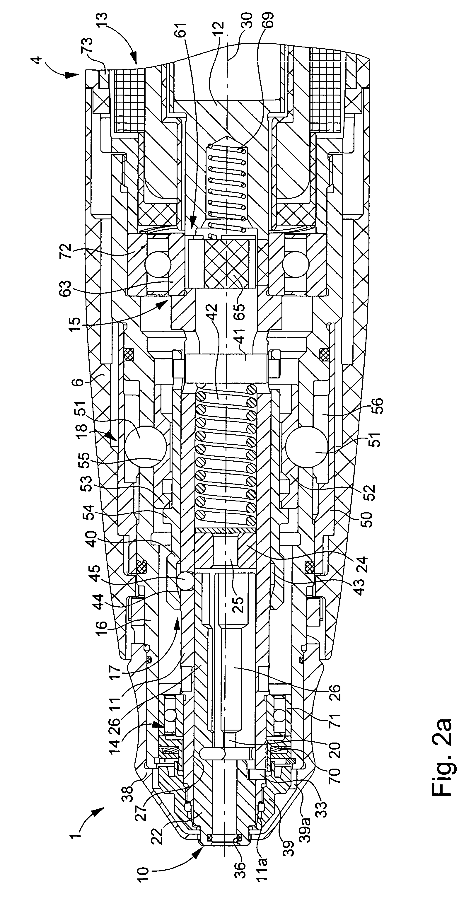
[0011]However, according to a preferred embodiment, the tightening mechanism has a sliding sleeve mounted around the hollow shaft and for each lever of the clamp has a transmission element disposed in a radial hole of the hollow shaft between said supporting surface of the lever and an internal cam surface of the sliding sleeve, the cam surface having an axially inclined surface such as a conical surface. This sliding sleeve can be biased in the gripping direction by a relatively weak spring. In a particularly advantageous variant, a recess forming a notch, which holds the sliding sleeve in place by the elasticity of the levers of the clamp, can be provided in the cam surface, and this enables the usual tightening spring to be omitted. Consequently, the release action no longer has to overcome the axial pressure resulting from this spring.

Problems solved by technology

Moreover, a relatively strong tightening spring has a relatively high weight and this constitutes a particular disadvantage for a piece, which rotates very quickly and the centring of which cannot generally be assured with precision.
The resulting vibrations increase with the weight of this spring.
This device does not require an axial tightening spring, but the centrifugal force, however, tends to release the clamp.

Method used


Image

  • Handpiece for dental or surgical use
  • Handpiece for dental or surgical use
  • Handpiece for dental or surgical use

Examples


Embodiment Construction

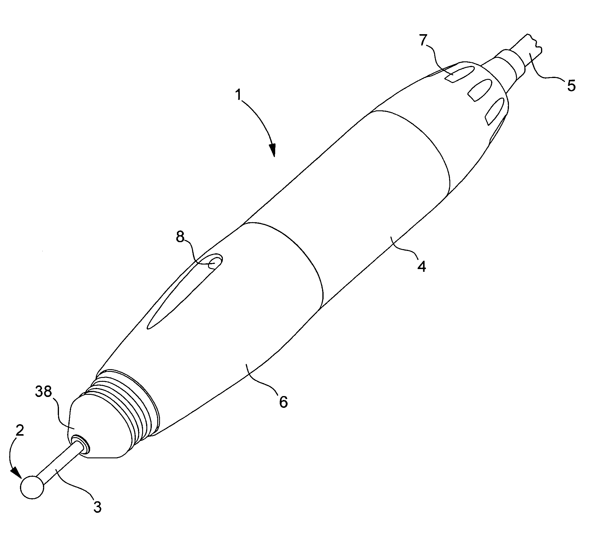
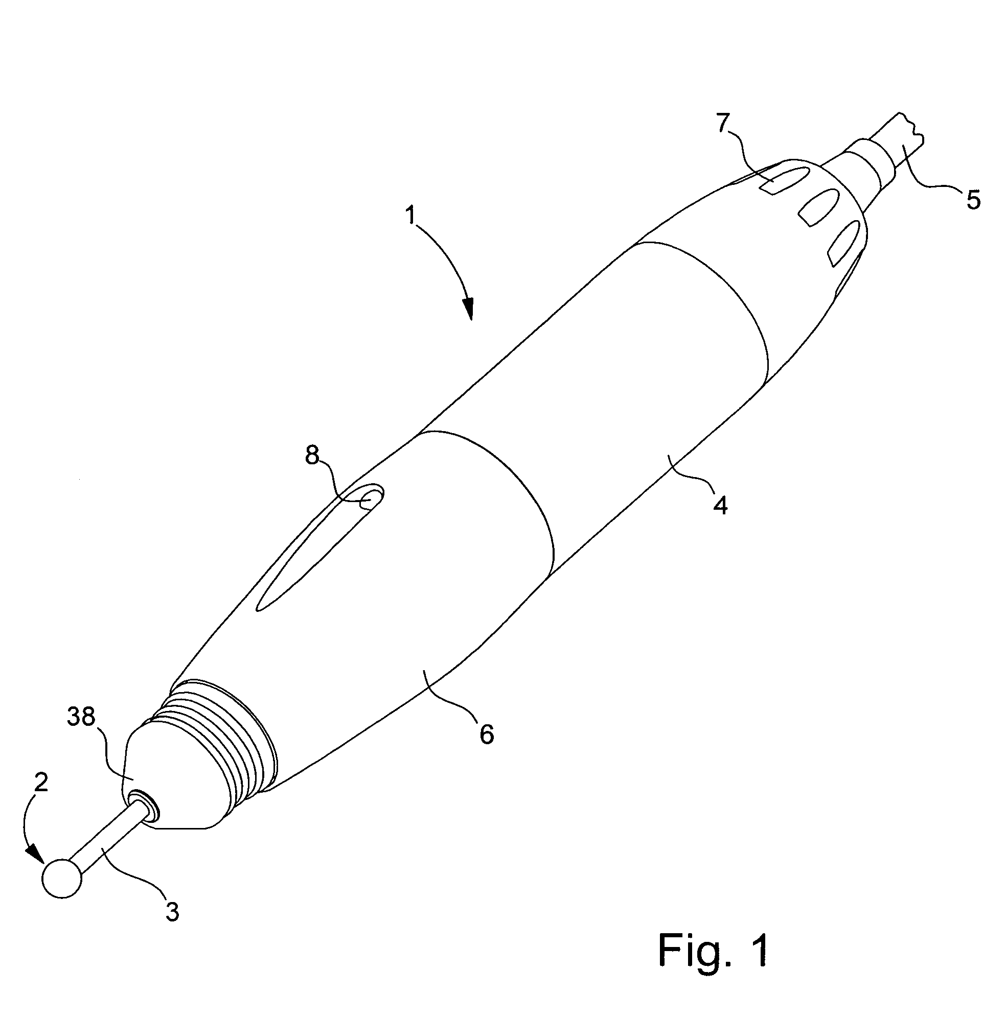
[0024]FIG. 1 shows a handpiece 1 for dental or surgical use, in which various embodiments of the invention may be seen, which will be described further below. The handpiece is fitted with a removable rotatable tool 2 with a cylindrical shank 3, which is gripped in a rotatable clamp of handpiece 1. This contains a motor, i.e. an electric motor, to cause tool 2 to rotate at high speed. The motor is housed in the main body 4 of the handpiece and is supplied with power and controlled from an external unit via an electric cable 5 connected to the rear of the handpiece. The operator controls the tightening and release of the clamp by causing a sleeve 6 rotatably mounted on body 4 to rotate in one direction or the other. References 7 and 8 refer to vents. Such an instrument finds application in particular in dental practices, dental laboratories and in microsurgical techniques. In the examples shown here, it is an instrument for a dental laboratory using tools having a shank with a standar...


PUM


Abstract

At the front, a handpiece (1) has a clamp (10) fitted to tightly grip the shank of a removable tool housed in guide holes (23, 25). The clamp has two or more levers (26) attached to an annular section (22) of the clamp by elastic joints (27), each of which has a gripping jaw (20) to grip the tool shank. On each lever, the gripping jaw (20) is located much closer to the joint (27) than to a supporting surface, on which a tightening mechanism (17) exerts a centripetal force so that the lever multiplies this force. The tightening mechanism preferably has a sliding sleeve (40) having a conical inside surface (44), which produces the force at the levers of the clamp by means of balls (45) housed in the holes of a hollow rotatable shaft (11).

Description

[0001]This application claims priority from European Patent Application No. 04003487.8 filed Feb. 17, 2004, the entire disclosure of which is incorporated herein by reference.BACKGROUND OF THE INVENTION[0002]The present invention relates to a handpiece for dental or surgical use of the type comprising: a hollow shaft, which is rotatable around a longitudinal axis and mounted by bearings in a fixed tubular sheath; a clamp mounted in a front end of the hollow shaft and having a central channel intended to receive the shank of a removable tool, the clamp having axial arms arranged around said axis, each of which are provided with a gripping jaw in the central channel, and each arm being attached to an annular section of the clamp; a tightening mechanism supported by the hollow shaft and arranged to exert a centripetal force on a supporting surface of each arm of the clamp to grip the tool shank between the gripping jaws of the clamp; and a release mechanism supported at least partially...

Claims


Application Information

Patent Timeline
Patent Type & Authority Patents(United States)
IPC IPC(8): A61C1/14A61C3/00A61B17/16B23B31/20
CPCA61B17/162A61C1/144A61C1/147
Inventor MA TRE, LUC
Owner BIEN AIR HLDG SA
Learn More