
Magnetic sensing element including a pair of antiferromagnetic layers separated by spacer section in track width direction and method for fabricating same

a technology of antiferromagnetic layers and magnetic sensing elements, which is applied in the field of magnetic sensing elements, can solve the problems of weak magnitude of exchange coupling magnetic fields produced between ferromagnetic layers and exchange coupling layers, decrease in sensitivity to external magnetic fields, and side reading, so as to prevent side reading, improve read sensitivity, and narrow gap

Inactive Publication Date: 2007-05-01
TDK CORPARATION
View PDF4 Cites 5 Cited by
  • Summary
  • Abstract
  • Description
  • Claims
  • Application Information

AI Technical Summary

Benefits of technology

The technical effect of this patent is that it provides a new way to make a magnetic sensor that solves issues with current methods. This new design prevents interference between neighboring cells, improves sensitivity, reduces gaps between cells, and makes manufacturing easier.

Problems solved by technology

The patent text describes a magnetic transducer structure and a problem with depositing layers on an uneven surface. This results in a decrease in sensitivity to an external magnetic field and potential side reading. The technical problem is how to control the magnetizations of the ferromagnetic layers without depositing them on an uneven surface.

Method used


Image

  • Magnetic sensing element including a pair of antiferromagnetic layers separated by spacer section in track width direction and method for fabricating same
  • Magnetic sensing element including a pair of antiferromagnetic layers separated by spacer section in track width direction and method for fabricating same
  • Magnetic sensing element including a pair of antiferromagnetic layers separated by spacer section in track width direction and method for fabricating same

Examples


Embodiment Construction

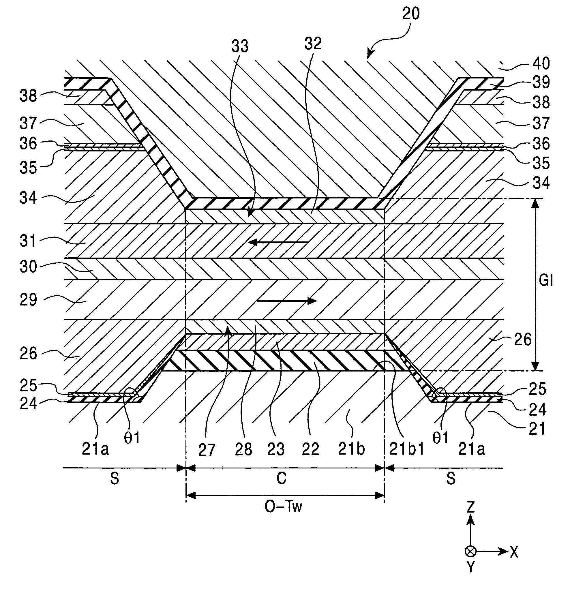
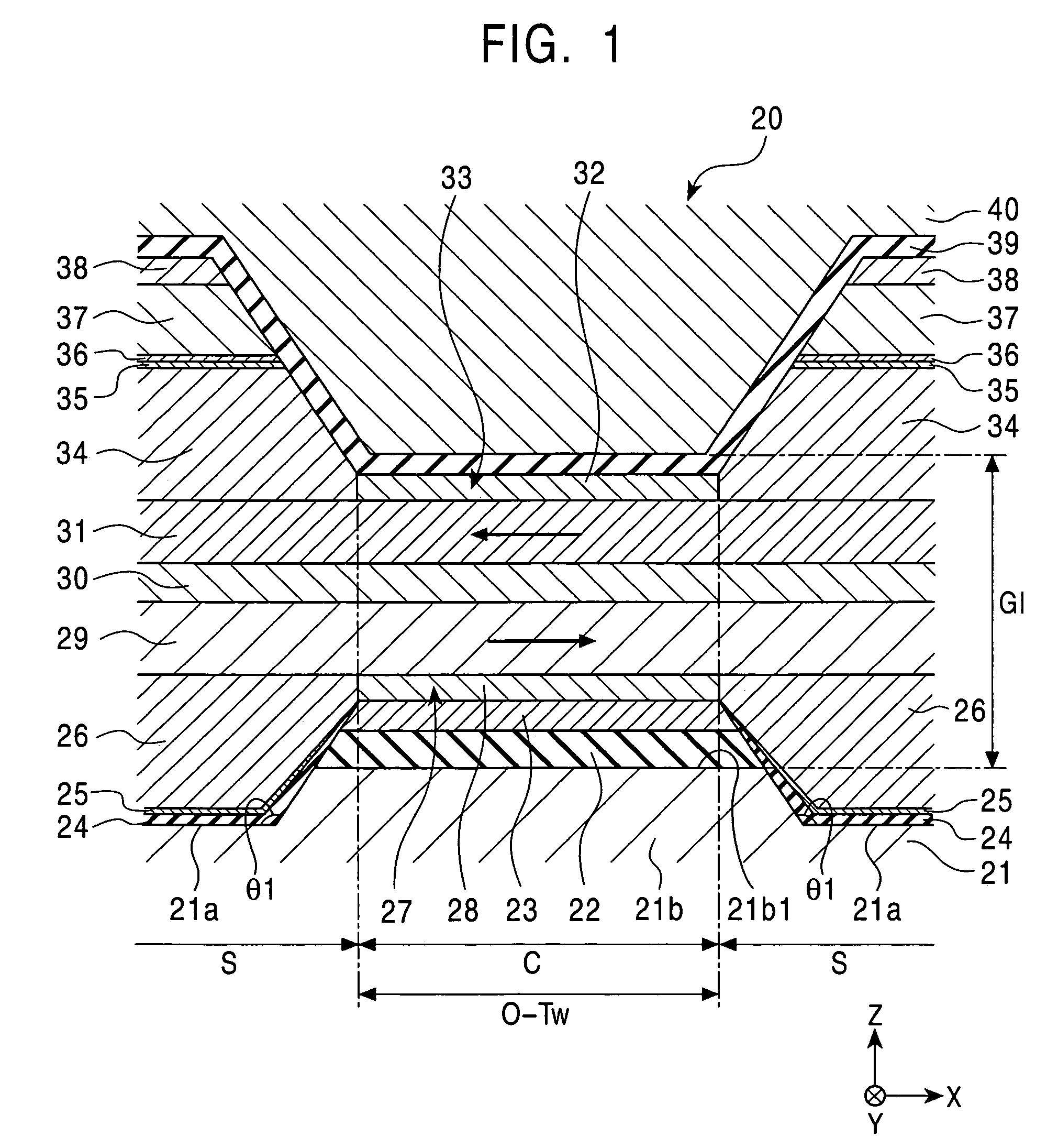
[0053]FIG. 1 is a partial sectional view which shows a magnetic sensing element in a first embodiment of the present invention, viewed from the surface facing a recording medium.

[0054]A magnetic sensing element 20 shown in FIG. 1 is a MR head for reading external signals recorded in the recording medium. The surface facing the recording medium is, for example, a planar surface that is perpendicular to the planes of the thin films constituting the magnetic sensing element 20 and parallel to the track width direction of the magnetic sensing element. In FIG. 1, the surface facing the recording medium corresponds to a planar surface parallel to the X-Z plane.

[0055]When the magnetic sensing element 20 is used for a floating-type magnetic head, the surface facing the recording medium corresponds to a so-called “air bearing surface (ABS)”.

[0056]The magnetic sensing element 20 is formed on the trailing end of a slider, for example, composed of alumina-titanium carbide (Al2O3—TiC). The slide...


PUM


Abstract

Disclosed are a magnetic sensing element in which side reading can be prevented, read sensitivity can be improved, and gap narrowing is enabled, and a method for fabricating the same. A magnetic sensing element includes a pair of first antiferromagnetic layers separated by a first spacer section. A first spacer layer is disposed in the first spacer section. The first spacer layer has the same composition as that of the first antiferromagnetic layers, and has a disordered crystal structure with a thickness that is smaller than that of the first antiferromagnetic layers. A first free magnetic layer is disposed on the continuous surface including the upper surfaces of the first antiferromagnetic layers and the first spacer layers. The magnetic sensing element also includes a nonmagnetic interlayer, a second free magnetic layer, and a pair of second antiferromagnetic layers separated by a second spacer section on the second free magnetic layer.

Description


Claims


Application Information

Patent Timeline
Owner TDK CORPARATION
Learn More