
Leathered steering wheel

Inactive Publication Date: 2007-05-01
TOYODA GOSEI CO LTD +1
View PDF6 Cites 9 Cited by
  • Summary
  • Abstract
  • Description
  • Claims
  • Application Information

AI Technical Summary

Benefits of technology

[0011]The invention is to solve the above mentioned problems, and accordingly it is an object of the invention to provide a steering wheel enabling to increase abrasion resistance by suppressing the protrusions at the parts of combining the mutual leather materials in the leather layer, and to easily take the countermeasures against alterations in stitching positions of the leather materials.
[0014]the leathered wheel of the invention is characterized in that the respective end portions of the leather material are structured with thin portions formed by thinning the back sides of said end portions, such that thickness around stitching portions is reduced, while the length from the part to be stitched to the end of the leather material is set such that said length is substantially equal to a thickness of a main portion of said leather material, and an end face of said end is contacted to the covered layer.
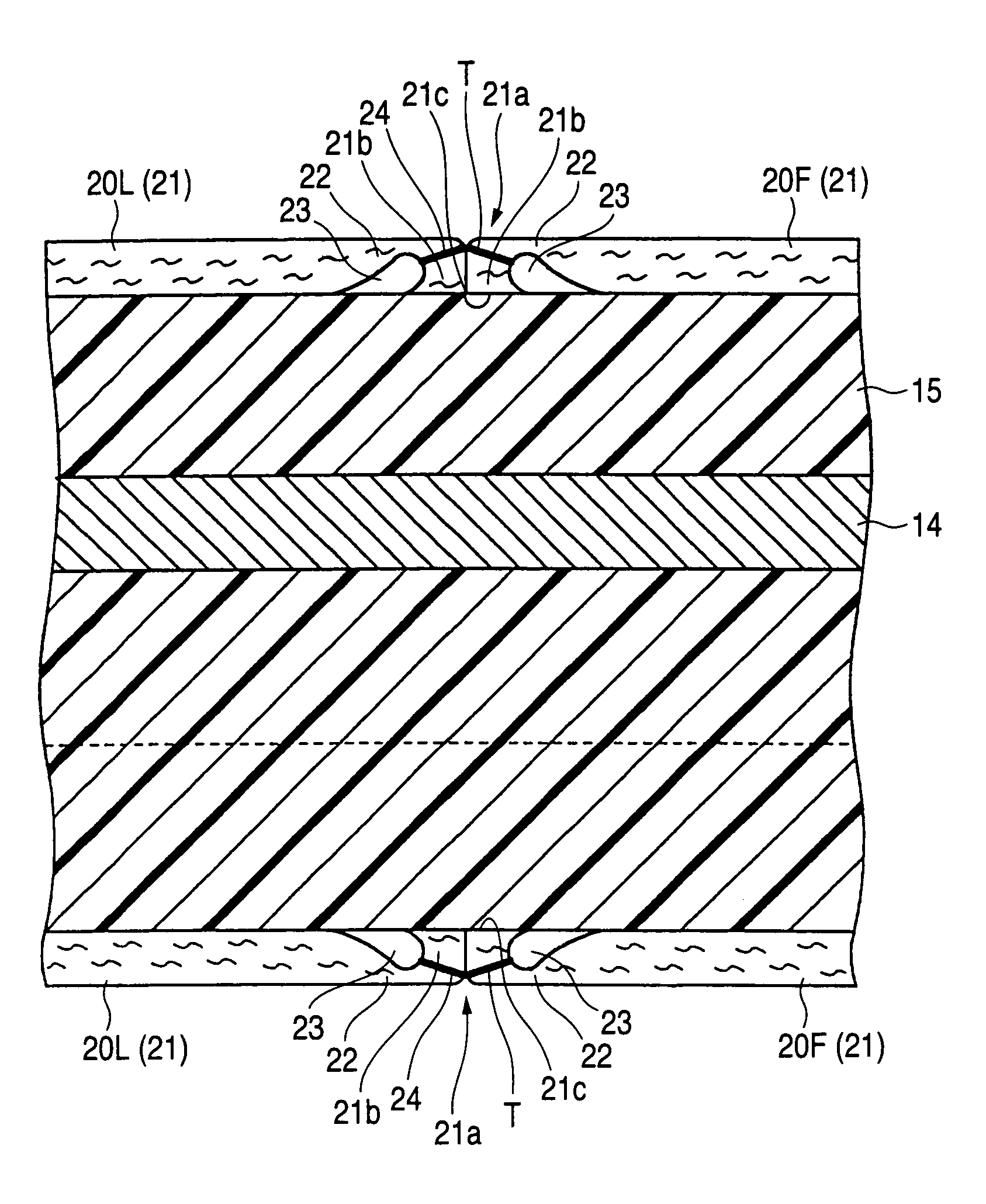
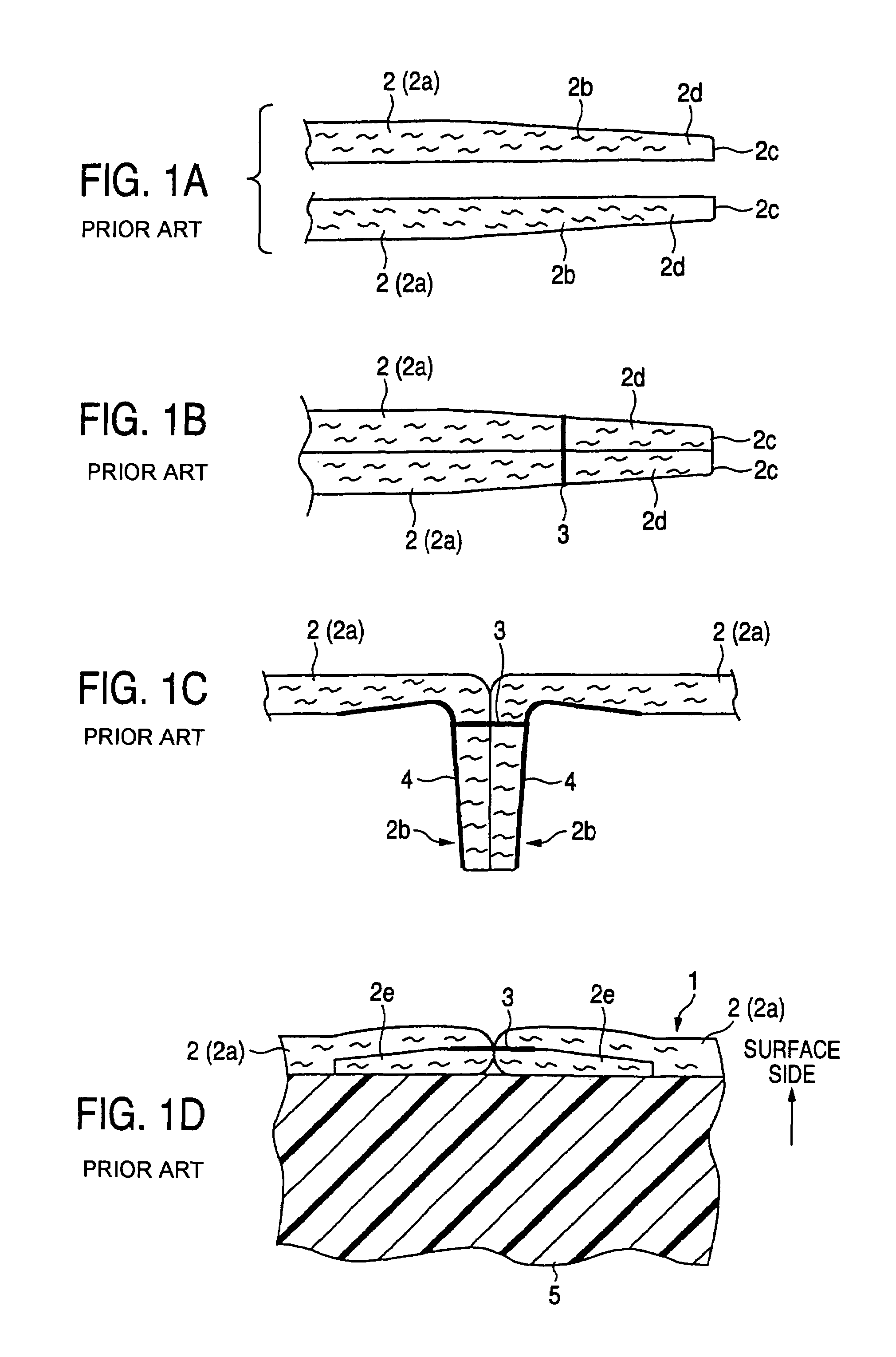
[0015]As to the above structured leathered steering wheel, the end of the leather materials contact the covered layers at end faces, and the length from the stitching portion to the end of the leather material is set to be substantially equal to the thickness of the main portion of the leather material. That is, in the leathered steering wheel of the invention, since the end of the leather material is not turned down as the related art shown in FIG. 1, the thickness of the leather layer can be made almost uniform including parts around the stitching portion without making the thickness large around the stitched part. Further, the leathered steering wheel of the invention has the structure arranged with the thin portion of the leather material around the end thereof. Therefore, when the leather layer is placed at the outer circumference of the covered layer, the end of the leather material enters into a recess defined in the thin portion thereof. As a result, in the leather layer, the protrusion of the stitching portion can be more suppressed.
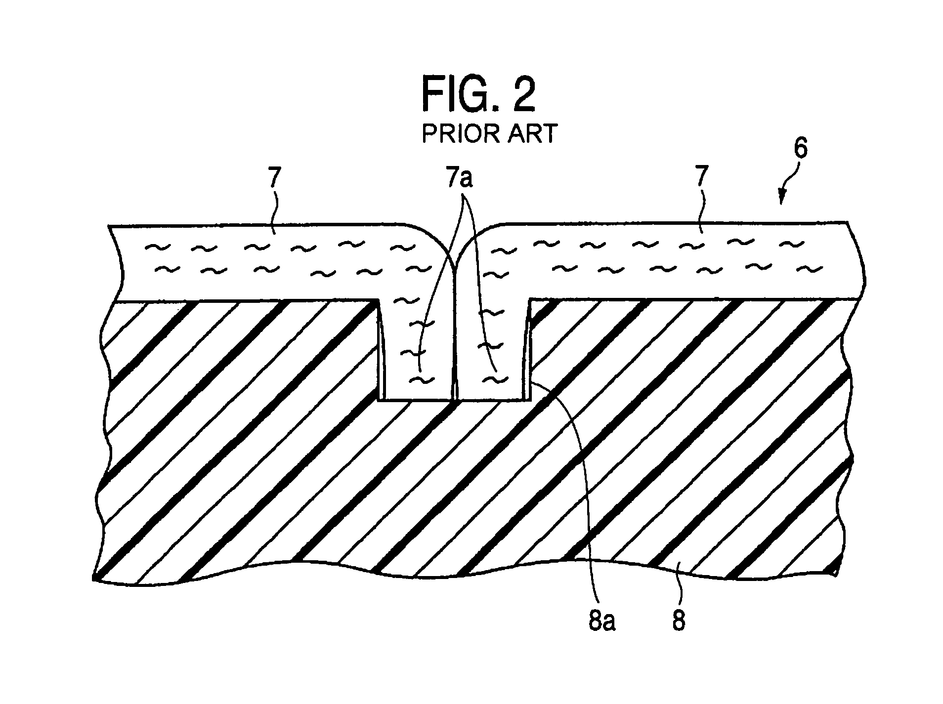
[0016]Further, in the leathered steering wheel of the invention, since it is any longer unnecessary to turn down and adhere the end of the leather materials as the related art shown in FIG. 1, the production processing number and cost therefor may be lowered. In addition, in the leathered steering wheel of the invention since the covered layer does not need the groove portion as the related art shown in FIG. 2, when altering stitching portions of the leather materials, any designing alterations in the covered layer are not requisite, and it is easy to take the countermeasures against alterations in stitching positions of the leather materials.
[0017]Accordingly the leathered steering wheel of the invention enables to increase abrasion resistance by suppressing the protrusion at the part of combining the leather materials in the leather layer, and to easily take the countermeasures against alterations in stitching positions of the leather materials.
[0019]With such a structure of the leathered steering wheel, since the thickness of the end of the leather material is larger than the thickness of the stitching portion, the end of the leather material is difficult to slip out from a stitching thread at the stitching portion, so that the leather layer can increase tensile strength. In the above structured leathered steering wheel, the position more recessed than the end of the leather material is stitched, and since stitching portions can be easily seen, stitching works are desirable.

Problems solved by technology

However, in case the leather layer 6 is so structured, the groove portion 8a is necessarily defined in the covered layer 8 for fitting the ends 7a of the leather materials 7, and therefore, when changing the positions of combining the leather materials 7 in the ring part, designing alterations as a metal mold are accordingly necessary for forming the covered layer 8, and countermeasures therefore are not easy.

Method used


Image

  • Leathered steering wheel
  • Leathered steering wheel
  • Leathered steering wheel

Examples


Embodiment Construction

[0027]The invention will be explained on the basis of one embodiment as follows.

[0028]The leathered steering wheel W of the embodiment comprises, as shown in FIG. 3, a ring part R to be held while steering, a boss part B at the center of the ring part, and four spoke parts S connecting the ring part R and the boss part B, and at these respective parts, a steering wheel core 11 is disposed for connecting the members one another. That is, the steering wheel core 11 is, as seen in FIG. 3, composed of a boss part core 12 disposed at the boss part B, spoke part cores 13 at the respective spoke parts S, and a ring part core 14 at the ring part R.

[0029]As to the steering wheel core 11, a central boss 12a of the boss part core 12 connected to a steering shaft is steel-made, while a boss protecting part 12b around a boss 12a of the other boss part core 12, spoke part cores 13, and the ring part core 14 are formed via a die cast using light alloys as Mg alloy or Al alloy.

[0030]Around the ring...


PUM


Abstract

In a leathered steering wheel, a leather layer is so arranged as to cover a covered layer of a ring part, and the leather layer is formed by stitching, along the circumferential direction of the ring part, a plurality of leather materials to one another, and the end portions of the leather material are structured with thin portions formed by thinning the back sides of the end portions such that thickness around stitching portions is lowered, wherein a length L1 from the stitching portion to the end face of each leather material is set to be substantially equal to or slightly smaller than a thickness t1 of a main portion of the leather material, and the end face is brought into abutment to the covered layer.

Description

[0001]The present application is based on Japanese Patent Application No. 2002-188209, the entire contents of which are incorporated herein by reference.BACKGROUND OF THE INVENTION[0002]1. Field of the Invention[0003]The present invention relates to a leathered steering wheel for steering a vehicle, and in particular, to a leathered steering wheel in which the outer circumference is covered with a leather layer in a ring part.[0004]2. Related Art[0005]Conventionally, as shown in Japanese Patent Publication No. 2000-43736A, there is a leathered steering wheel of a structure of an outer circumference of the ring part covered with the leather layer allover. In this kind of steering wheels, a core of the ring part is arranged on the circumference of the wheel. And the core is covered with a covered layer of a soft synthetic resin, and the leather layer is placed to cover the outer circumference of the covered layer.[0006]In the leathered steering wheel of such a structure, the leather l...

Claims


Application Information

Patent Timeline
IPC IPC(8): B62D1/06
CPCB62D1/06Y10T74/2087
Inventor ADACHI, YUICHISHIMIYA, SHINSUKE
Owner TOYODA GOSEI CO LTD
Learn More