
Air-intake duct system for a combustion engine

a technology of air intake ducts and combustion engines, which is applied in the direction of combustion air/fuel air treatment, air intakes for fuel, non-fuel substance addition to fuel, etc., can solve the problems of not providing the integration of all the known devices to reduce pollutants or fuel consumption, and the air intake duct system has a relatively high weight and many assembly steps, so as to achieve the effect of low mechanical finishing work, low cost and high weigh

Inactive Publication Date: 2007-04-24
PIERBURG GMBH & CO KG NEUSS
View PDF13 Cites 16 Cited by
  • Summary
  • Abstract
  • Description
  • Claims
  • Application Information

AI Technical Summary

Benefits of technology

[0008]A further integration, in particular for pollutant reduction, is achieved in that the exhaust gas recirculation duct is divided in the direction of flow by a dividing wall essentially into two parallel ducts open on one side perpendicular to the flow direction, whereby the first duct serves as a cooling duct and the second duct serves as a bypass duct, and the housing of the exhaust gas recirculation duct features an opening into which a bypass valve that is embodied as a plug-in valve can be plugged. Through the division of the exhaust gas recirculation duct into the cooling duct and the bypass duct, optimized exhaust gas temperatures can be achieved with the aid of the bypass valve, according to the operating state of the combustion engine. The cold start and warm-up periods of the engine are hereby shortened. The embodiment of the bypass valve as a plug-in valve entails a further integration with simultaneous weight and production cost reduction.
[0023]Due to the great integration of all components, cost advantages arise through the lack of intersections and supports as well as the low amount of mechanical finishing work required. This air-intake duct system excels in its weight, which is distinctly reduced in comparison with known embodiments, through which a reduced fuel consumption arises. Additionally an improved exhaust gas quality is achieved. Through this integrated module, the extent of testing at the customer's site is also distinctly reduced since only a testing of the entire module is necessary. The plug-in valves can be used for different engines without further adjustment, which reduces production and development costs. Since the individual parts are optimally matched to one another, the assembly of the total system is extremely facilitated and thus costs are additionally reduced.

Problems solved by technology

Accordingly, this air-intake duct system has a relatively high weight and many assembly steps are needed to connect the individual parts.
Moreover, there is no integration of all the known devices to reduce pollutants or fuel consumption.
Although such an embodiment reduces the number of production steps, it has the disadvantage that the exhaust gas is conducted through the cooler in each operating state of the combustion engine and an integration of further components is not provided.

Method used


Image

  • Air-intake duct system for a combustion engine
  • Air-intake duct system for a combustion engine
  • Air-intake duct system for a combustion engine

Examples


Embodiment Construction

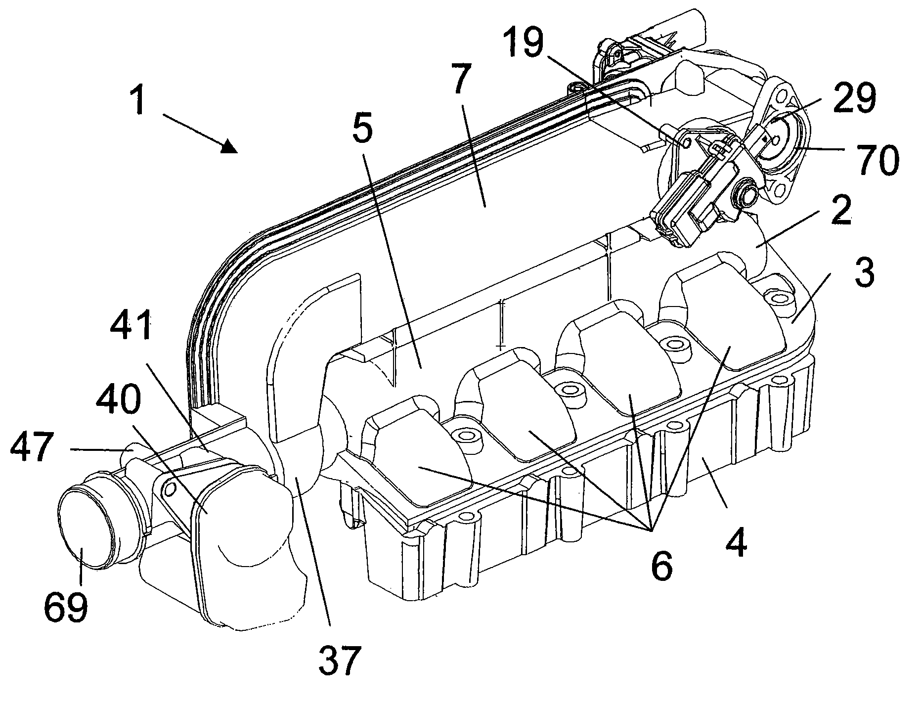
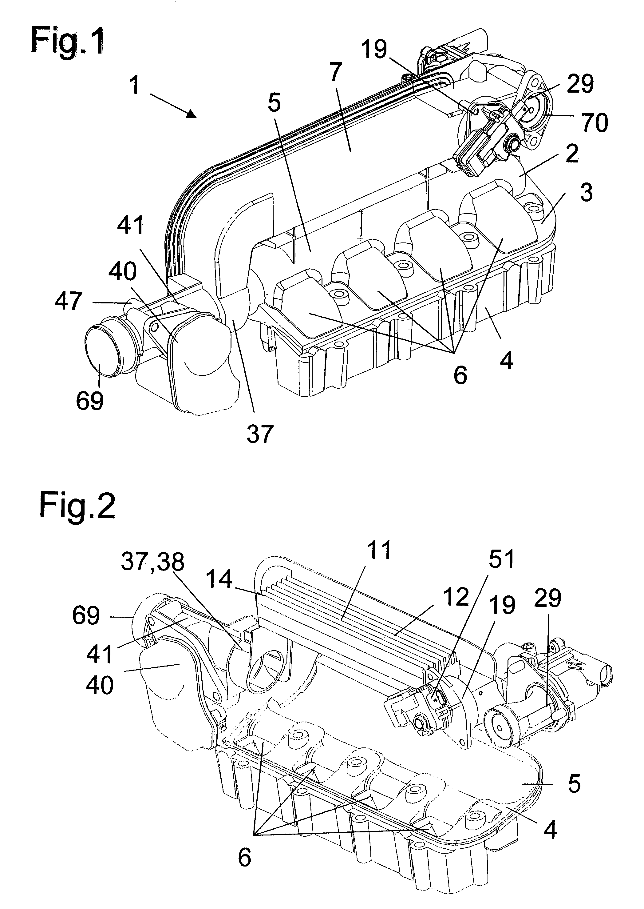
[0035]The air-intake duct system 1 according to the invention shown in FIG. 1 features a two-part housing 2 comprising an upper shell 3 and a lower shell 4, which shells are welded together during assembly, e.g. via the friction stir welding method. In the assembled state the upper shell 3 and the lower shell 4 form an intake plenum duct 5 and individual air inlet ducts 6 leading to the cylinders of a combustion engine, whereby in the present exemplary embodiment an air-intake duct system 1 for a four-cylinder combustion engine with two inlet valves per cylinder is shown, so that four air inlet ducts 6 are shown.

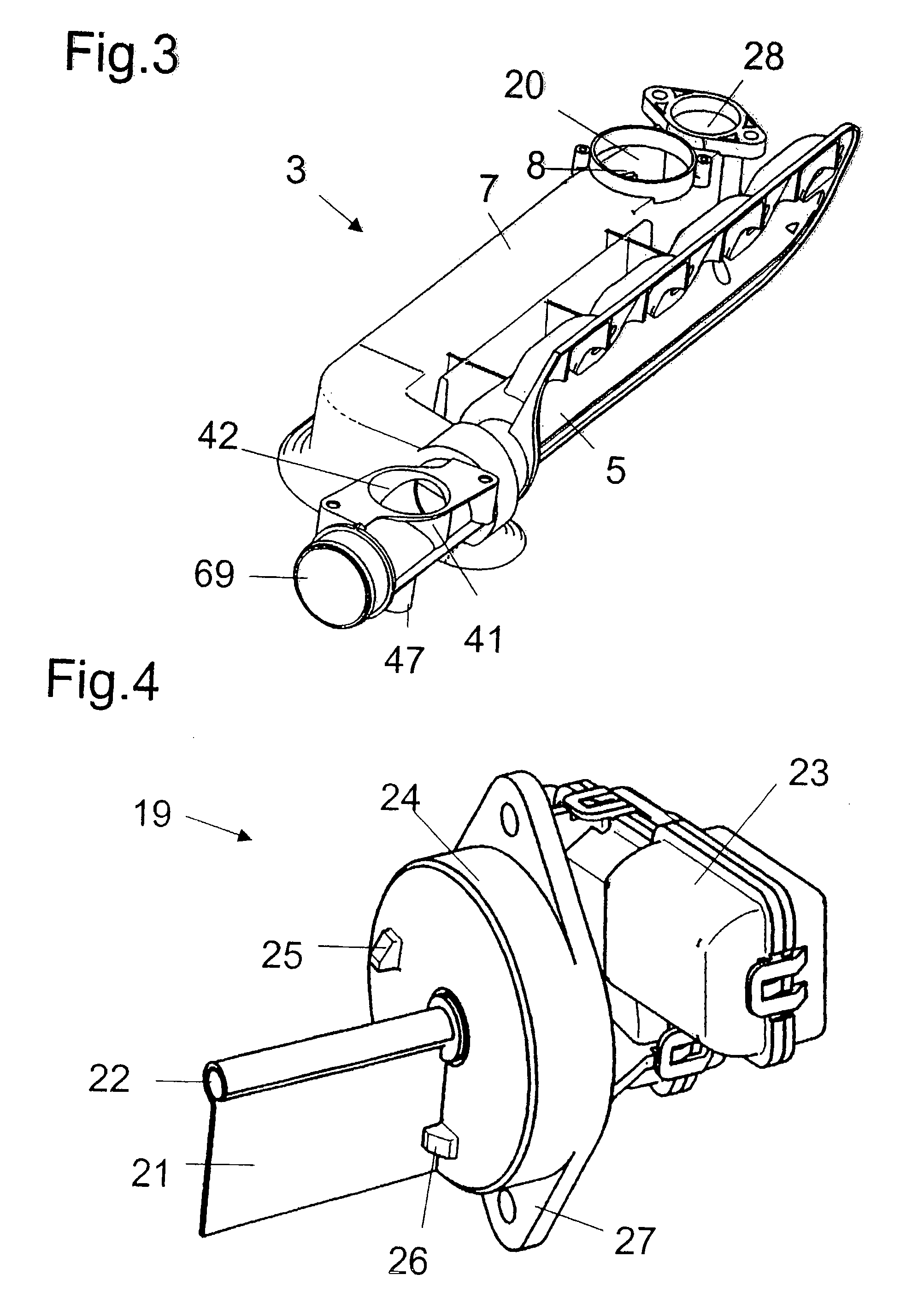
[0036]The upper shell 3 shown in FIG. 3 is produced by the aluminum die casting method and features, in addition to the ducts 5, 6 partially embodied therein, an exhaust gas recirculation duct 7 open on one side perpendicular to the flow direction, which duct is produced in one piece with the upper shell 3, so that additional supports are omitted, as a result of which the nu...


PUM

PropertyMeasurementUnit
shapeaaaaaaaaaa
weightaaaaaaaaaa
exhaust gas temperaturesaaaaaaaaaa

Abstract

The invention relates to an air-intake duct system (1) in which a throttle valve (40), an exhaust gas recirculating valve (29), a bypass valve (19), an exhaust gas cooler (11), against which exhaust gas flows via bypass valve (19), and, optionally, an air mass sensor are integrated. A complete intake unit for modern engines is hereby created, with which achieves a charging optimization and thus a reduction in fuel consumption as well as a reduction in pollutants by a corresponding thermal management in the engine by the exhaust gas cooler (11) that, together with a shell (3, 4) of the housing (2), is manufactured as a single piece. The individual add-on pieces (12, 19, 29, 40, 59) are optimally matched to one another and have, due to their designs, a low weight and a low finishing work requirement. This makes it possible to distinctly reduce assembly and manufacturing costs.

Description

[0001]This is a National Phase Application in the United States of International Patent Application No. PCT / EP2004 / 009713 filed Sep. 1, 2004, which claims priority on German Patent Application No. DE 103 41 393.6, filed Sep. 5, 2003. The entire disclosures of the above patent applications are hereby incorporated by reference.FIELD OF THE INVENTION[0002]The invention relates to an air-intake duct system for a combustion engine.BACKGROUND OF THE INVENTION[0003]Air-intake duct systems for combustion engines, exhaust gas recirculation valves, exhaust gas coolers, exhaust gas feeding devices, and throttle valves and their function are generally known and are described in a large number of patent applications. In recent years attempts have been made to better match the individual parts of a total intake system and exhaust gas recirculation system and to make available complete units from one source in the smallest possible installation space.[0004]A corresponding system is described, for ...

Claims


Application Information

Patent Timeline
Patent Type & Authority Patents(United States)
IPC IPC(8): F02M25/07C04B28/02C04B28/06C04B28/34C09K8/467F02M35/10F02M35/112
CPCF02B31/085F02D9/109F02M25/0726F02M25/0773F02M35/10222F02M35/112F02M25/0772Y02T10/121Y02T10/146F02M26/22F02M26/53F02M26/54Y02T10/12F02M35/10F02M35/104
Inventor KUHNEL, HANS-ULRICHSANDERS, MICHAELSCHURFELD, ARMINTHONNESSEN, DIETER
Owner PIERBURG GMBH & CO KG NEUSS
Learn More