
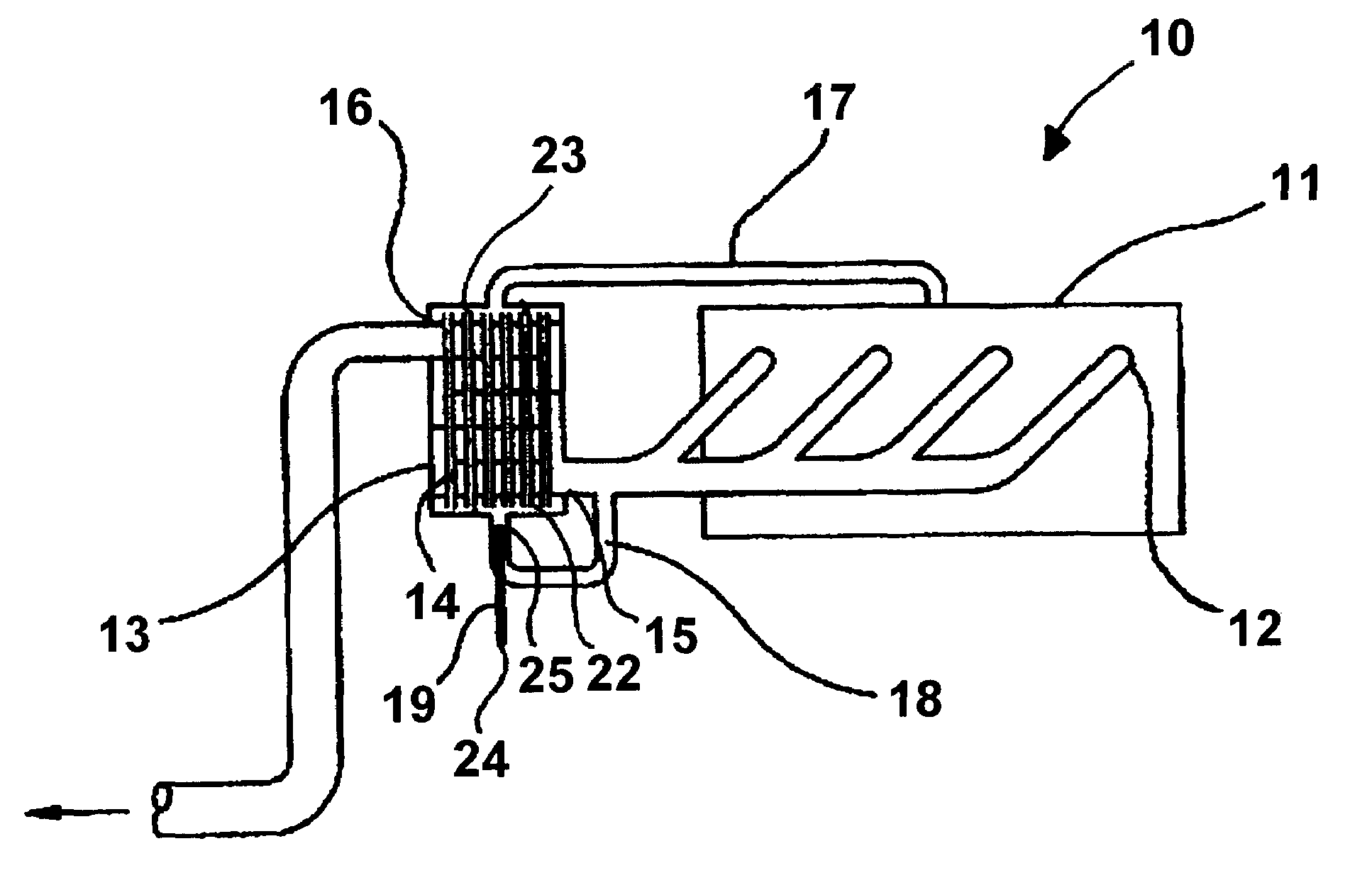
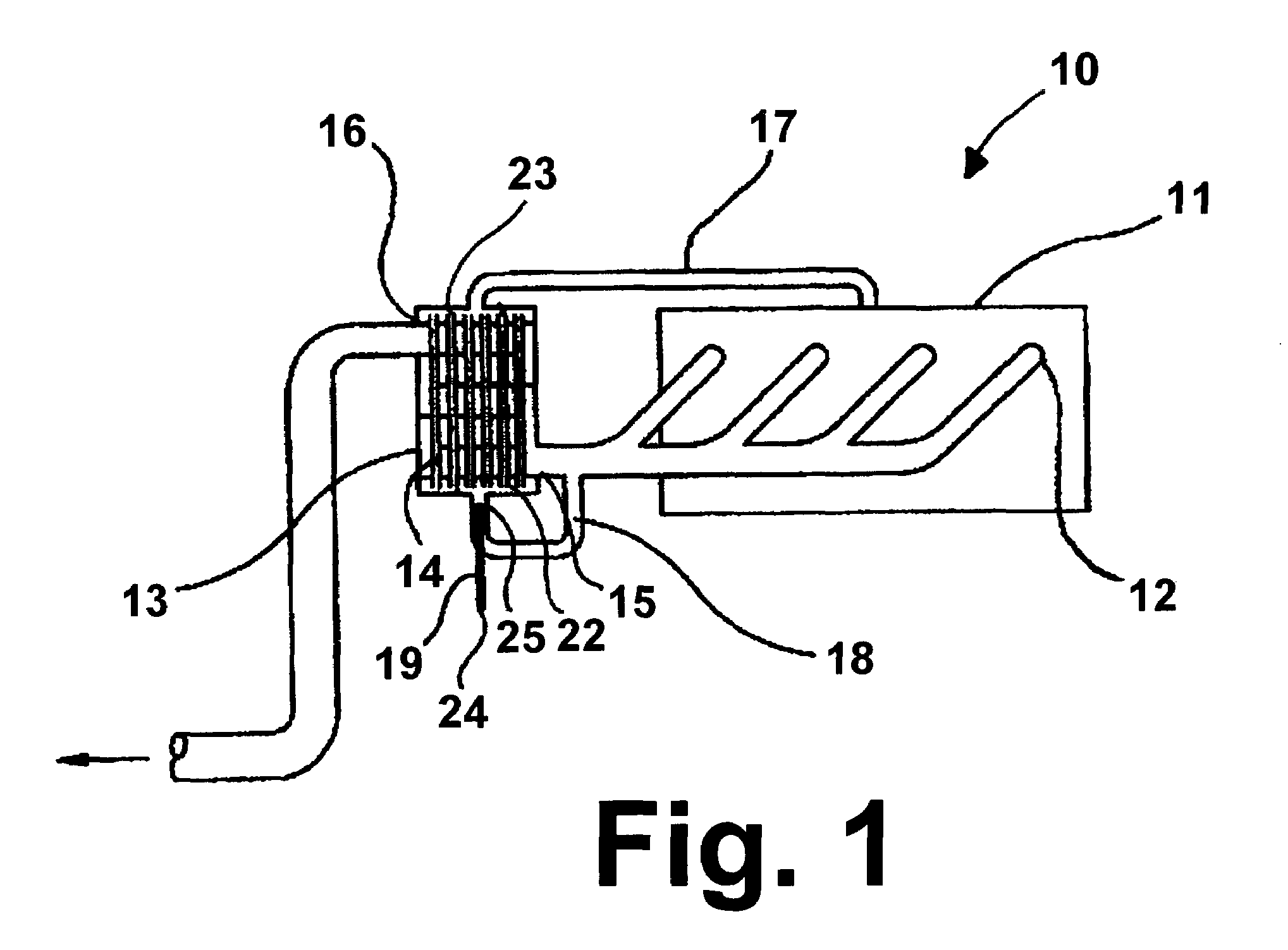
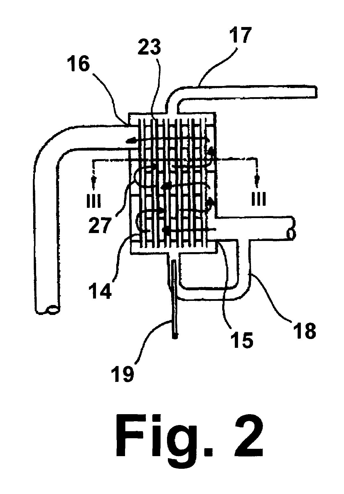
Catalytic core reactor for thermochemical heat recovery

a core reactor and thermochemical technology, applied in the direction of machines/engines, mechanical equipment, combustion air/fuel air treatment, etc., can solve the problems of reaction consumption, increased efforts, and often large heat rejection of thermal processes, so as to increase the heating value of fuel, reduce operating costs, and increase engine efficiency

Inactive Publication Date: 2007-04-24
UTILIZATION TECH DEV NFP
View PDF7 Cites 23 Cited by
  • Summary
  • Abstract
  • Description
  • Claims
  • Application Information

AI Technical Summary

Benefits of technology

[0016]It is another object of this invention to provide a method for thermally decomposing organic fuels into mixtures of hydrogen and carbon monoxide and using for that purpose waste heat, rejected by the engine, to increase the heating value of the fuel, thereby increasing engine efficiency, reducing operating costs, and diminishing greenhouse emissions.

Problems solved by technology

Thermal processes often reject large amounts of heat.
Since the invention of these engines, efforts have been ongoing to increase their mechanical efficiency; and as fuel costs increase, these efforts become more urgent.
When reforming a fuel, thereby producing large percentages of hydrogen and carbon monoxide, the reaction is endothermic; that is, the reaction consumes heat.
As a result, sensible heat is consumed in the reforming reaction.
Notwithstanding the apparent attractiveness of using thermochemical fuel conversion for increasing the efficiency of engines and reducing emissions output, the proposed energy recovery and improved thermal efficiency methods have not found widespread use due to a number of technical problems.
One of the major problems is a lack of thermochemical fuel conversion systems suitable for use in vehicular applications.

Method used


Image

  • Catalytic core reactor for thermochemical heat recovery
  • Catalytic core reactor for thermochemical heat recovery
  • Catalytic core reactor for thermochemical heat recovery

Examples


Embodiment Construction

[0026]The invention disclosed herein is a fuel conversion reactor concept that is adapted to the specific requirements of a thermochemical fuel conversion process with special considerations for on-board vehicle installations. In addition to vehicular applications, the reactor concept can also be used for a wide range of other catalytic processes. This process is characterized by low reaction temperatures, typically in the range of about 500° F. to about 1500° F., and can take place at high pressures as is customary in reforming processes or at low pressures such as in thermal decomposition reactions. In fuel reforming, a catalyst is employed to facilitate the reversible reaction of methane with steam to form hydrogen and carbon monoxide. The reactor is particularly well suited for conditions where one reactant operates at a significantly lower pressure than the other reactant. With the heat transfer and catalyst configurations of the reactor of this invention, several advantages ar...


PUM


Abstract

A fuel conversion system having an exhaust gas generator, such as an engine or a furnace, having a heated exhaust gas outlet, a reactor vessel having a heated exhaust gas inlet in fluid communication with the heated exhaust gas outlet, having a cooled exhaust gas outlet, and containing at least one reactor tube having an exhaust gas inlet in fluid communication with the heated exhaust gas outlet, a convertible fuel inlet, and a converted fuel outlet, and a monolithic fuel conversion catalyst structure substantially centered within the at least one reactor tube and shaped to form at least one flow channel between the monolithic fuel conversion catalyst structure and an inside wall of the at least one reactor tube.

Description

BACKGROUND OF THE INVENTION[0001]1. Field of the Invention[0002]This invention relates to thermochemical conversion of hydrocarbon and other organic fuels to produce hydrogen and carbon monoxide. More particularly, this invention relates to method and apparatus for thermochemically converting hydrocarbon and other organic fuels to produce hydrogen and carbon monoxide in which hot exhaust gases from internal combustion engines, furnace exhaust gases and the like are utilized as heating media or reactants in the conversion process. As used herein, the terms “thermochemical conversion” and “thermochemically converting” refer to processes in which the hydrocarbon and / or other organic fuels are reformed or thermally decomposed. This invention also relates to an apparatus for thermochemically converting hydrocarbon and other organic fuels which may be suitable for vehicular installation and use. This invention further relates to a catalytic reactor for thermochemically converting hydrocar...

Claims


Application Information

Patent Timeline
IPC IPC(8): F02B51/02
CPCC01B3/26C01B3/384F01N5/02F02M25/0742F02M25/12F02M27/02C01B2203/0233C01B2203/0277C01B2203/066C01B2203/0811C01B2203/1023F01N3/2889F01N2240/02F01N2240/30F01N2330/34Y02T10/121Y02T10/16F02M26/36Y02T10/12Y02P20/10
Inventor HEMSATH, KLAUS HEINRICH
Owner UTILIZATION TECH DEV NFP
Learn More