
Electrical connector element with rewirable spring contacts

a technology of spring contact and electrical connector, which is applied in the direction of electrically conductive connection, coupling device connection, electrical apparatus, etc., can solve the problems of complex and costly solutions, insufficient to ensure the minimum safety distance required by current international safety,

Active Publication Date: 2007-04-17
IND LOMBARDA MATERIALE ELETTRICO I L M E
View PDF3 Cites 18 Cited by
  • Summary
  • Abstract
  • Description
  • Claims
  • Application Information

AI Technical Summary

Benefits of technology

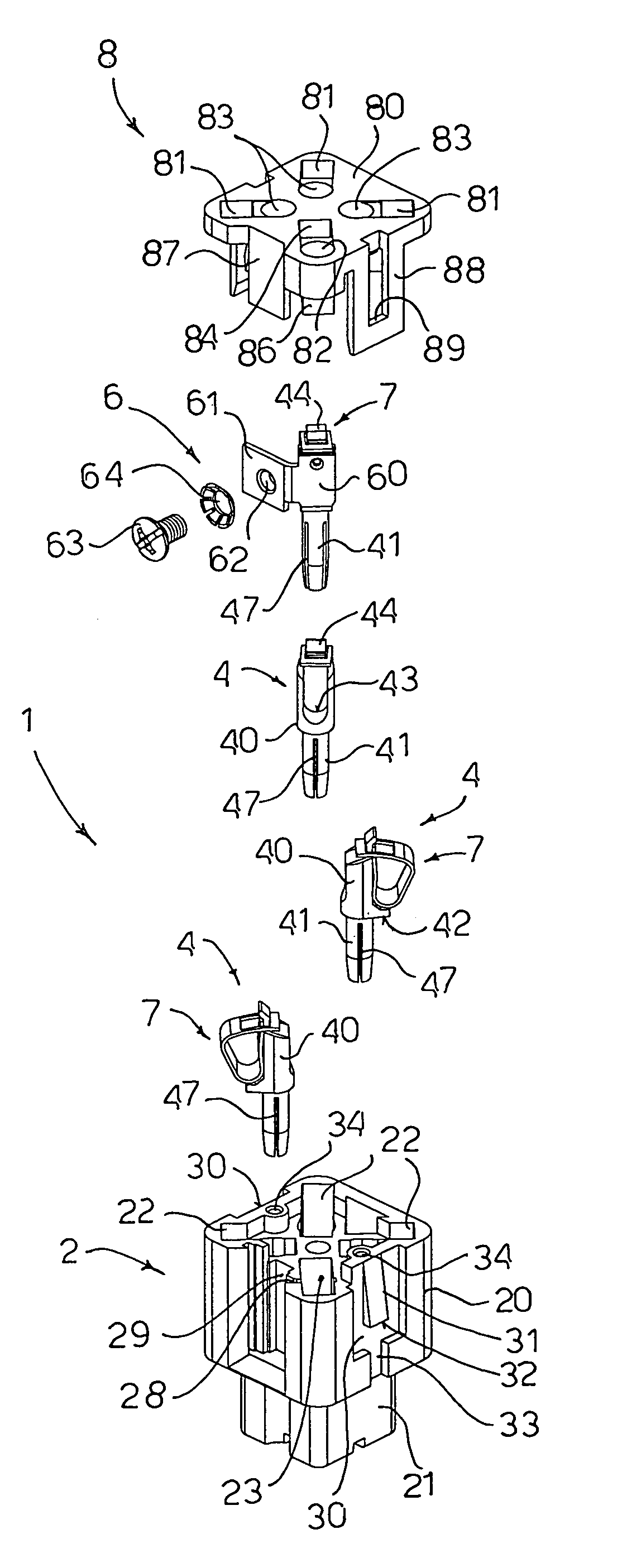
[0012]The object of the present invention is to eliminate the drawbacks of the prior art by providing an electrical connector element with rewirable conductors, maintaining the size of standard connector elements, which is interconnectable therewith and at the same time can also be used with very high rated voltages.
[0013]Another object of the present invention is to provide an electrical connector element with rewirable conductors which ensures an efficient, effective and safe conductor clamping system which at the same time is cheap, easy to produce and easy to assemble.

Problems solved by technology

In both cases, the distance between the head of the clamping screw, or the conductor of the feed cable, and the wall of the metal case is sufficient to ensure electrical insulation for connectors used at rated voltages of 250 V, but it is not sufficient to ensure the minimum safety distance required by current international safety standards for connectors used at rated voltages of 400 V.
This solution is rather complex and costly, because of the provision of an additional element to be inserted into very limited spaces.

Method used


Image

  • Electrical connector element with rewirable spring contacts
  • Electrical connector element with rewirable spring contacts
  • Electrical connector element with rewirable spring contacts

Examples


first embodiment

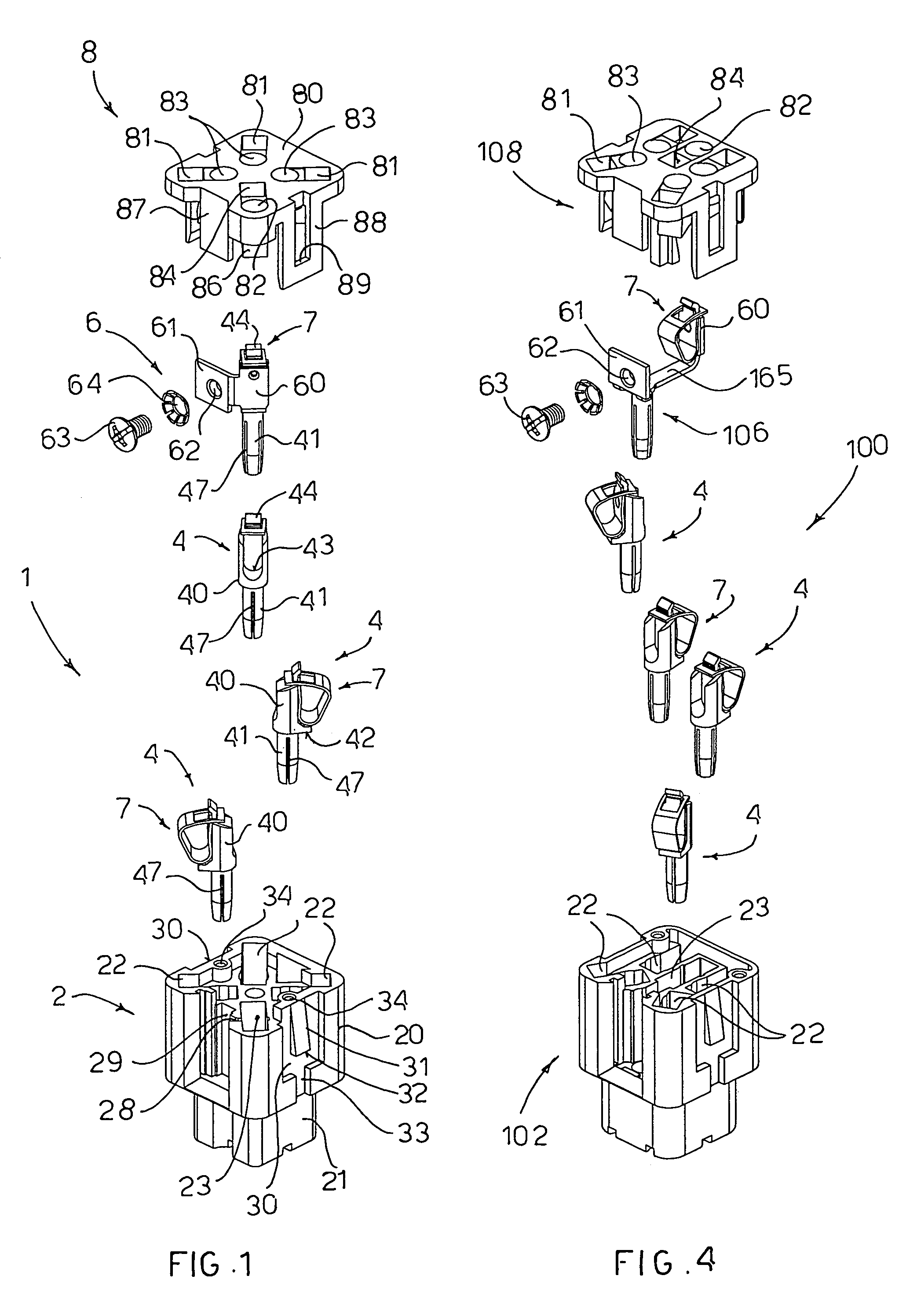
[0057]FIG. 5 shows a connector element 200 having three male pole contacts 204 and a male earth contact 206. The male contacts 204 and 206 are like the contacts 4 and 6 of the female connector element 1, except for the bottom part 246 of the contact which has a full cylindrical shape adapted to engage inside the hollow bottom part 46 of the female contacts 4 and 6.

[0058]In this case, the bottom part 221 of the body 202 is slightly modified. In fact the bottom part 221 of the body 202 is hollow on the inside and downwardly open to receive the bottom part 21 of the body 2 of the female connector element 1 in a coupling relationship. A square gasket 9 is provided which is disposed between the two bottom parts 21 and 221 of the two bodies 2, 202 to provide a seal between them.

[0059]The cover 8 of the connector element 200 is the same as that of the connector element 1.

second embodiment

[0060]FIG. 6 illustrates a connector element 300 having four male pole contacts 204 like those of the connector element 200 and a male earth contact 306 like the earth contact 106 of the connector element 100 of the second embodiment, but having a male bottom part 246.

[0061]In this case, the body 302 has a top part like that of the body 102 of the connector element 100, comprising four seats 22 for the pole contacts, disposed near the four corners of the body 302, a central elongated seat 23 for the earth contact and a bottom part 221 like that of the connector element 200. The cover 108 of the connector element 300 is like that of the connector element 100 of the second embodiment.

[0062]In all the connector elements illustrated, the springs 7 are made of conductive metal material and are disposed in the respective seats 22 and 23 of the bodies 2, 102, 202 and 302, completely insulated from the outside. In fact the bodies 2, 102, 202 and 302 are made of insulating plastic material a...


PUM


Abstract

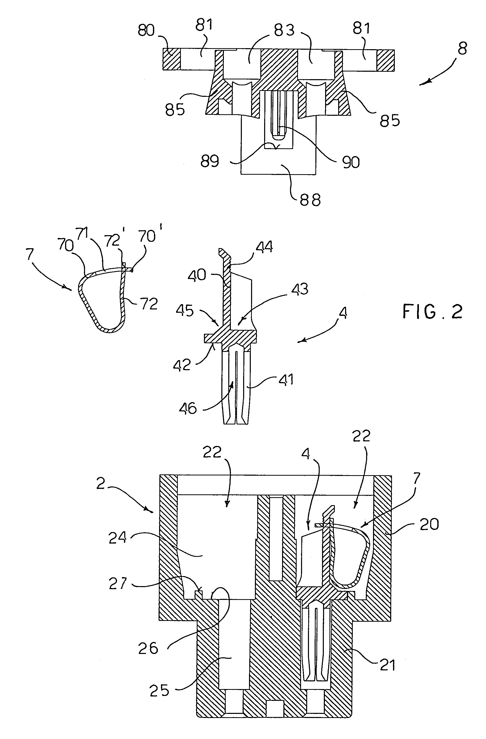
A standard type electrical connector element (1; 100; 200; 300), with a square cross-section measuring about 21×21 mm, includes (2; 102; 202; 302) within which are formed seats (22) adapted to house contacts (4; 204) adapted to receive the conductors (50) of electrical feed cables; a seat (23) adapted to house a contact (6; 106; 206; 306) adapted to go into contact with the conductor of an electrical earth cable, a cover (8; 108) which can be coupled on the body and which is provided with holes (83, 82) disposed in register with the contacts (4; 204) to allow the conductors of the feed and earth cables to be inserted, and spring elements (7) disposed in the seats (22, 23) of the body in which the contacts are housed to clamp the conductors of the electrical cables in contact with the respective contacts.

Description

BACKGROUND OF THE INVENTION [0001]The present invention refers to an electrical connector element with rewirable contacts, wherein the feed cable conductors can be inserted removably into the terminals of the connector element.[0002]In the field of connectors for industrial environments various market standards have become consolidated over time in terms of size, number of poles and rated voltages. Amongst these there are connectors measuring 21 mm×21 mm, with 3 or 4 poles plus an earth contact, for currents of 10 A and a rated voltage of 250V. These connectors are provided with plastic or metal cases, are produced by numerous manufacturers and are generally mechanically and electrically interconnectable with each other.[0003]A research is currently under way among manufacturers to put onto the market connectors that are able to work with increasingly high rated voltages, though maintaining the same dimensions as the connectors of the standard type used until now and being interconn...

Claims


Application Information

Patent Timeline
IPC IPC(8): H01R4/48
CPCH01R4/4827H01R2107/00H01R24/62H01R4/4842H01R4/4816H01R4/48275
Inventor GERMANI, EMILIO
Owner IND LOMBARDA MATERIALE ELETTRICO I L M E
Learn More