
Rotary cutting bit with material-deflecting ledge

a cutting bit and ledge technology, applied in the field of cutting tools, can solve the problems of high rate of wear at the shank, limited life, and high prone to wear on the ledge of such a cutting bit, and achieve the effects of simple manufacturing, enhanced life, and less manufacturing operations

Inactive Publication Date: 2007-04-17
SANDVIK INTELLECTUAL PROPERTY AB
View PDF26 Cites 154 Cited by
  • Summary
  • Abstract
  • Description
  • Claims
  • Application Information

AI Technical Summary

Benefits of technology

[0007]It would be desirable to provide a cutting bit with an erosion-resistant structure which has an enhanced life. It would also be desirable to provide a cutting bit that is simple to manufacture and involves relatively few manufacturing operations.

Problems solved by technology

However, during the cutting of relatively softer material, such as asphalt, coal, and salt, the highest rate of wear occurs at the shank, i.e., erosion caused by cut asphalt rubbing and impacting against the shank.
Despite being formed of hard material, the ring will be subjected to considerable erosion by cuttings and thus will have a somewhat limited life.
However, it has been found that the ledge in such a cutting bit is highly prone to wear.

Method used


Image

  • Rotary cutting bit with material-deflecting ledge
  • Rotary cutting bit with material-deflecting ledge
  • Rotary cutting bit with material-deflecting ledge

Examples


Embodiment Construction

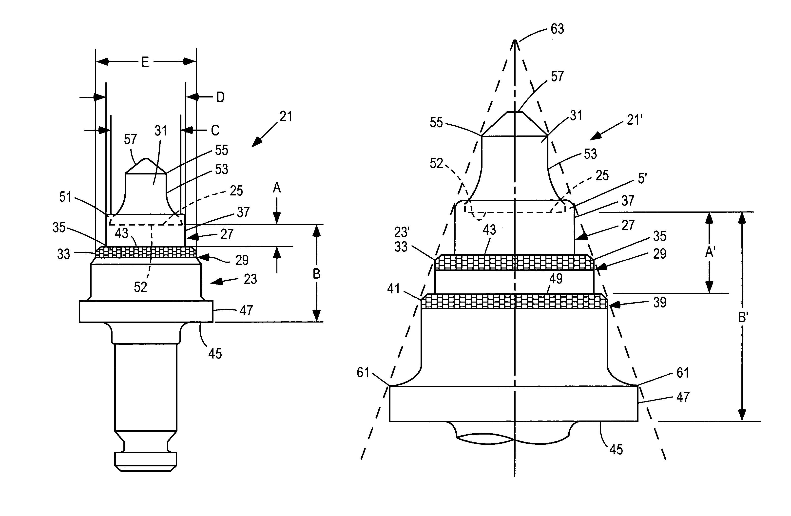
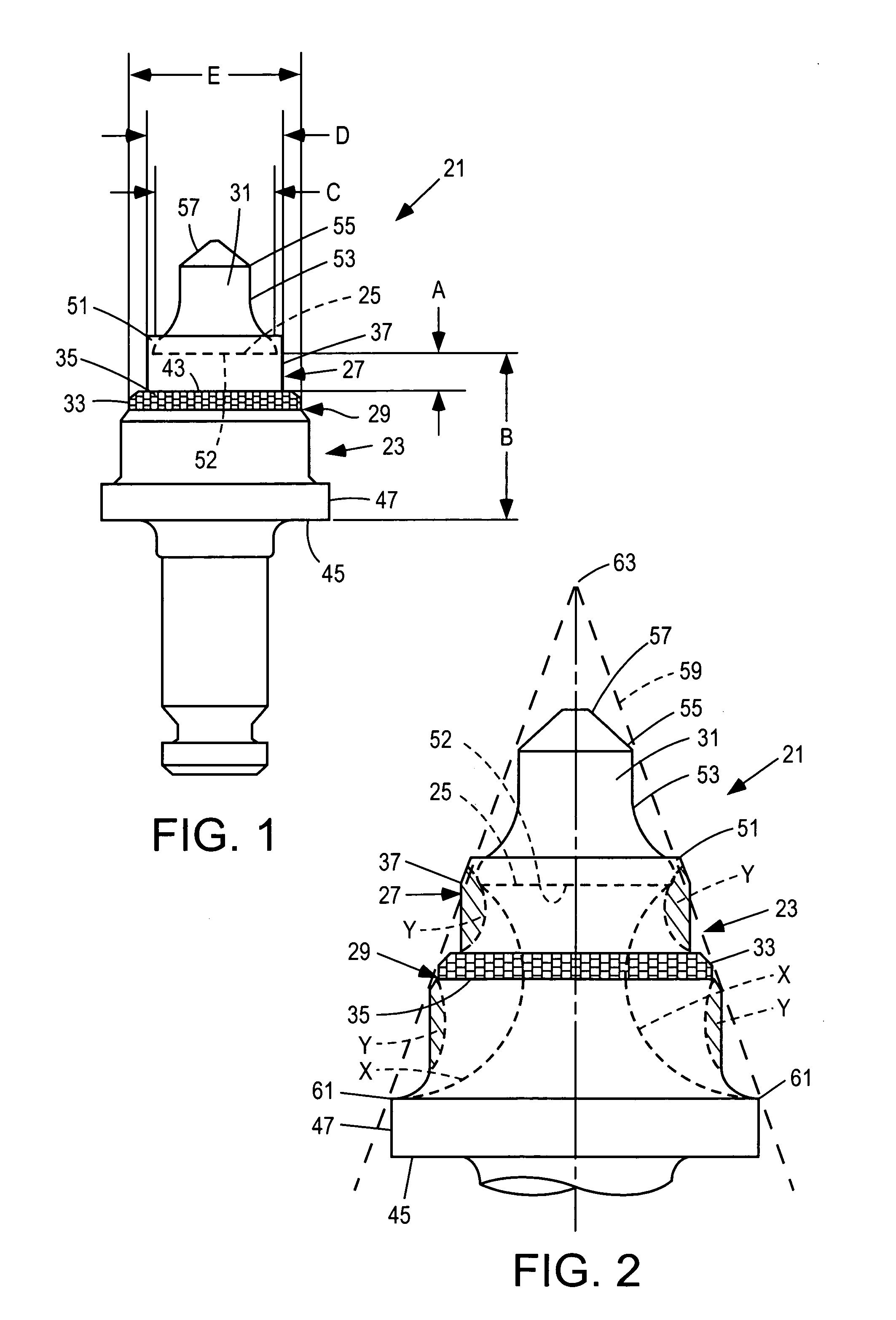
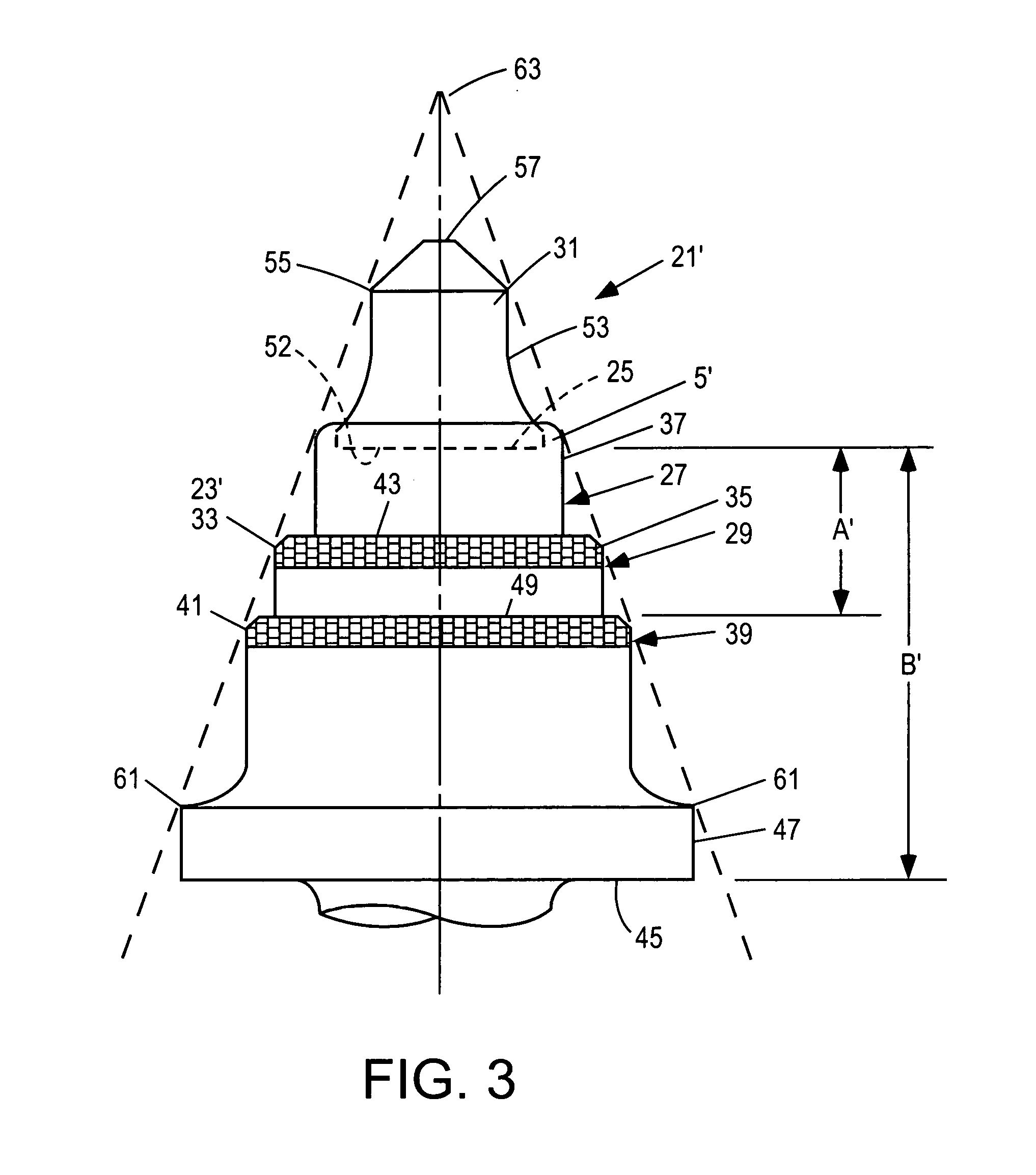
[0019]A cutting bit 21 according to an embodiment of the present invention is shown in FIGS. 1 and 2. The cutting bit 21 includes a body 23 having a front surface 25 and a side surface 27. The side surface 27 includes a shoulder 29 below the front surface 25 and extending substantially perpendicular to a central axis of the body. A cutting tip 31 is preferably attached to the front surface 25, usually by brazing, the cutting tip preferably being harder than the body 23.

[0020]A ring 33 that is preferably harder than the body 23 is attached to the body at a front surface 35 of the shoulder 29, such as by brazing. The body 23 is preferably no larger in diameter above the shoulder 29 than at the shoulder and, preferably, at least a portion 37 of the side surface 27 of the body 23 is cylindrical, more preferably circularly cylindrical, above the shoulder 29 so that a ring having a circular inside diameter can be slid over the body to the shoulder. Because the body 23 is preferably no lar...


PUM

PropertyMeasurementUnit
ninety degree angleaaaaaaaaaa
distanceaaaaaaaaaa
diameteraaaaaaaaaa

Abstract

A cutting bit includes a body having a front surface and a side surface, the side surface including a shoulder below the front surface and extending substantially perpendicular to a central axis of the body, and a ring that is harder than the body attached to the body at a front surface of the shoulder. Wear life of the cutting bit is enhanced by maintaining particular dimensional relationships regarding the position of the ring on the body, and the diameter of portions of the body.

Description

BACKGROUND AND SUMMARY[0001]The present invention relates to cutting tools used to cut through soft ground or through relatively soft material that has been laid on the ground, such as asphalt roadways.[0002]Mining, excavating, and road resurfacing operations are typically performed by forcing rotary cutting bits through the material being cut. The cutting bits are mounted on a driven support, such as a rotary drum, fixed beam, or the like to be forced through the material. A typical cutting bit comprises a hard cemented carbide tip that is brazed to the front surface of a steel shank. The shank is to be mounted in a holder by means of a retainer sleeve which permits the bit to rotate freely relative to the holder about the bit's center axis, while being restrained against axial dislodgment from the holder. Due to being freely rotatable, the tip is basically self-sharpening.[0003]It should be understood that cutting mechanisms of the type described above have been used to cut throug...

Claims


Application Information

Patent Timeline
Patent Type & Authority Patents(United States)
IPC IPC(8): E21C35/183B28D1/18E21C35/18
CPCB28D1/186E21C35/183E21C2035/1816E21C35/1837E01C23/127
Inventor MERCIER, GREGORY DAVIDFULLER, GARY A.
Owner SANDVIK INTELLECTUAL PROPERTY AB
Learn More