
Glass laminate substrate having enhanced impact and static loading resistance

a technology of static loading and glass laminate, applied in the field of electronic substrates, can solve the problems of limiting the application of plastic sheets in displays, reducing and reducing the application of organic light emitting materials used in oled displays, so as to enhance the loading resistance of substrates and increase the resistance to impact and static loading

Active Publication Date: 2007-04-10
CORNING INC
View PDF25 Cites 153 Cited by
  • Summary
  • Abstract
  • Description
  • Claims
  • Application Information

AI Technical Summary

Benefits of technology

The glass laminate substrate provides enhanced resistance to impact and static loading, maintains optical clarity, and reduces debris generation during processing, while allowing for reduced thickness and weight, thus overcoming the limitations of traditional glass substrates.

Problems solved by technology

Unfortunately, plastic sheets have three properties that limit their application in displays: a lower glass transition temperature, a lower transmission for visible light and a higher rate of gas permeability than glass sheets.
The gas permeability of a plastic sheet can lead to degradation of the organic light emitting materials used in OLED displays.
Such limitations restrict the application of plastic sheets in displays.

Method used


Image

  • Glass laminate substrate having enhanced impact and static loading resistance
  • Glass laminate substrate having enhanced impact and static loading resistance
  • Glass laminate substrate having enhanced impact and static loading resistance

Examples


example 1

[0041]

Eα (RT to setpoint,Glass(×106 psi)ν×10−6 / C)T* (C)Corning Code 173710.30.234.20671(core 70)Corning EAGLE2000 ™10.30.233.61671(skin layers 80, 90)

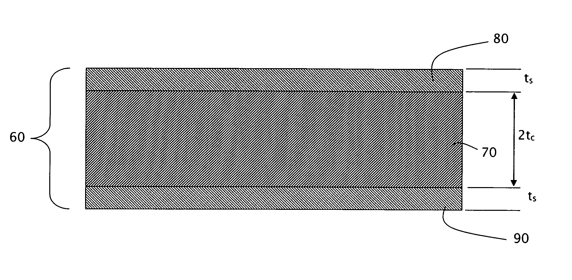
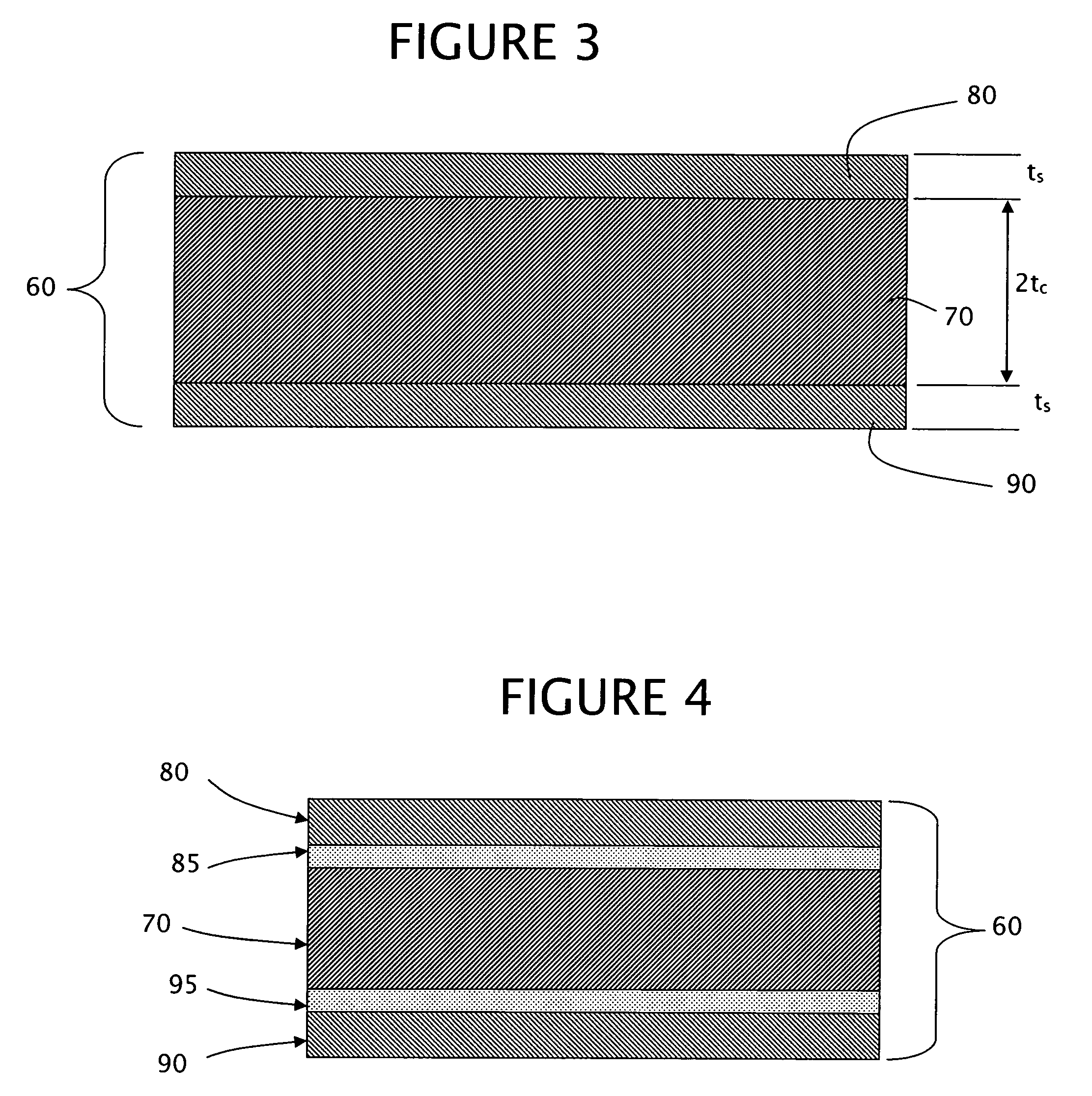
[0042]σs=-5098.6[1+tstc]σc=-5098.6[1+tcts]

[0043]

2(tc + ts)tctsσcσs(mm)(mm)(mm)tc / ts(psi)(psi)σs / σc1.10.4960.05399.197500−45999.1971.10.3880.16182.3991500−35992.3991.10.3340.21581.5492000−30991.5490.70.3160.03439.197500−45999.1970.70.2810.06864.0991000−40994.0990.70.2500.10002.51457−36422.50.70.2470.10302.3991500−35992.3990.70.150.20.752913−21850.750.40.180.01969.197500−45999.1970.40.1610.03924.0991000−40994.0990.40.050.20.333824−12750.33

example 2

[0044]

Eα (RT to setpoint,Glass(×106 psi)ν×10−6 / C)T* (C)Corning Code 70599.80.285.01598(core 70)Corning EAGLE2000 ™10.30.233.61671(skin layers 80, 90)

[0045]σs=-10919[1.0175+tstc]σc=10731[0.983+tcts]

[0046]

2(tc + ts)tctsσcσs(mm)(mm)(mm)tc / ts(psi)(psi)σs / σc1.10.5240.025620.479500−1024020.481.10.4990.05129.7481000−97489.741.14730.07676.1711500−92576.170.70.3340.016320.479500−1024020.480.70.3170.03269.7481000−97849.740.70.3010.04886.1711500−92576.170.70.2850.06504.3832000−87654.380.40.1910.009320.479500−1024020.480.40.1810.01869.7481000−97489.750.40.1720.02796.1711500−92576.17

example 3

[0047]

Eα (RT to setpoint,Glass(×106 psi)ν×10−6 / C)T* (C)Corning Code 031710.40.229.8581(core 70)Corning EAGLE2000 ™10.30.233.61671(skin layers 80, 90)

[0048]σs=-45888.5[0.997+tstc]σc=46037.5[1.003+tcts]

[0049]

2(tc + ts)tctsσcσs(mm)(mm)(mm)tc / ts(psi)(psi)σs / σc1.10.5260.023922.0162000−4402122.010.70.3310.019017.4122500−4352017.410.70.3230.026612.1513500−4251712.150.40.1910.008722.0162000−4402122.01

[0050]A representative glass laminate substrate 60 having elastic moduli Es and Ec of 10.3×10⁶ (pounds per square inch) psi (7.1×10⁴ MPa), Poisson's ratios νs and νc, of 0.22, T*=671° C., αc=37.8×10⁻⁷, αs=31.8×10⁻⁷, tc=0.30 mm, and ts=0.05 mm provides a residual compressive stress in the skin layer of 4,400 psi (30.3 MPa) and an internal tensile stress in the core 70 of 725 psi (5 MPa). Such laminate has a surface strength approximately 10% to 25% greater than a corresponding unlaminated core, as measured by the industry known ring-on-ring strength test. It has been observed that the internal t...


PUM

PropertyMeasurementUnit
residual compressive stressaaaaaaaaaa
residual tensile stressaaaaaaaaaa
residual compressive stressaaaaaaaaaa

Abstract

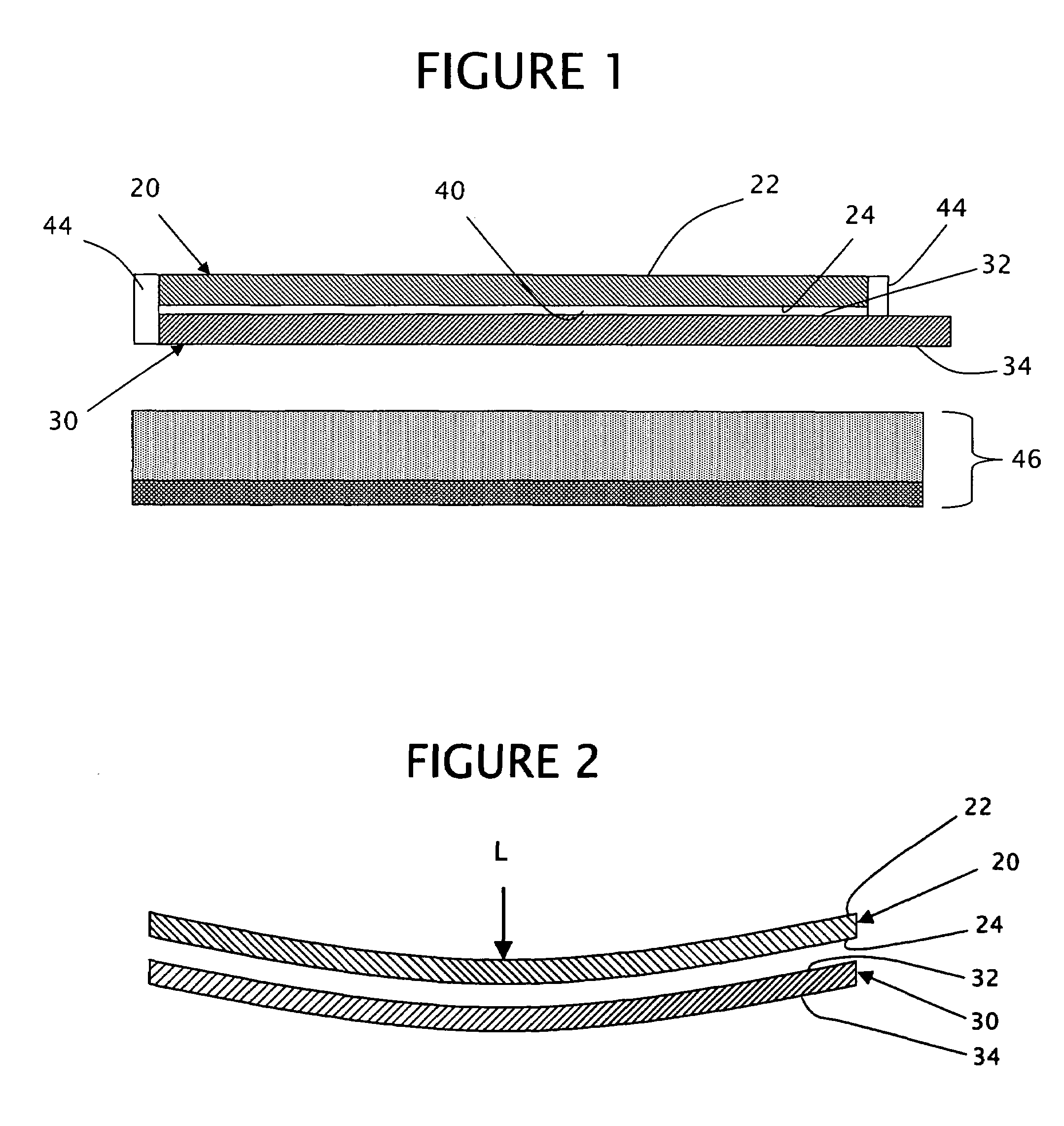
A glass laminate substrate for electronic substrates, such as flat panel displays, includes a transparent glass core bounded by transparent glass skin layers, wherein the coefficient of thermal expansion of the core is greater than the coefficient of thermal expansion of the skin layers thereby forming a residual compressive stress in the skin layers and a residual tensile stress in the core. The relative thickness of the skin layers can be selected to enhance the strength of the glass laminate substrate while maintaining a sufficiently low residual tensile stress in the core to allow scribing and separating of the substrate to size. Interlayers can be located between the core and the skin layers, wherein the interlayers include a residual compressive stress, and produce a reduced residual tensile stress in the core.

Description

BACKGROUND OF THE INVENTION[0001]1. Field of the Invention[0002]The present invention relates to electronic substrates and, more particularly, to a glass laminate substrate, such as for example use in flat panel displays, wherein selected layers in the substrate include a residual compressive stress or a residual tensile stress to enhance static and impact loading resistance of the substrate.[0003]2. Description of Related Art[0004]Glass substrates are often used in displays, such as for example liquid crystal displays (LCDs). LCDs have become increasingly popular for displaying information in calculators, watches, video games, audio and video equipment, portable computers and even car dashboards. The improving quality and size of LCDs has made the LCDs an attractive alternative to cathode ray tubes (CRTs) which are traditionally used in television sets and desktop computer displays. In addition, other flat panel display (FPD) types, such as plasma displays (PDs), field emission dis...

Claims


Application Information

Patent Timeline
Patent Type & Authority Patents(United States)
IPC IPC(8): B32B17/06C09K19/00
CPCB32B17/06C03B17/02C03B17/064C03B33/02C03B33/076C03C17/02Y10T428/10H01J2217/49264Y10T428/1059Y10T428/1068Y10T428/1064Y10T428/1095G02F2001/133302C09K2323/00C09K2323/05C09K2323/051C09K2323/053C09K2323/061G02F1/133302B32B13/04
Inventor GULATI, SURESH THAKORDASLAPP, JOSEF CHAUNCEY
Owner CORNING INC
Learn More