
Digital signal coding and decoding methods and apparatuses and programs therefor

a digital signal and signal technology, applied in the field of digital signal coding and decoding methods and apparatuses and programs therefor, can solve the problems of degrading the quality of the reconstructed signal, degrading the reconstructed signal, and not being able to achieve 1/3 or 1/4 compression ratio

Active Publication Date: 2007-04-03
NIPPON TELEGRAPH & TELEPHONE CORP
View PDF13 Cites 74 Cited by
  • Summary
  • Abstract
  • Description
  • Claims
  • Application Information

AI Technical Summary

Benefits of technology

[0016]It is therefore an object of the present invention to provide coding and decoding methods which prevent a bit erasure during transmission from leading to serious degradation of the decoded signal quality and apparatuses which embody the methods.
[0029]According to the coding method of the present invention, each piece of transmission / recording unit data is put in packet form, and hence, even if the amount of information is reduced by intentionally erasing the packet in accordance with the channel capacity or storage capacity during coding, the decoding method of the present invention enables the transmission / recording unit data to be compensated for the packet erasure.

Problems solved by technology

However, the loss depends on the coding condition or the input signal, and may sometimes lead to degradation of the reconstructed signal.
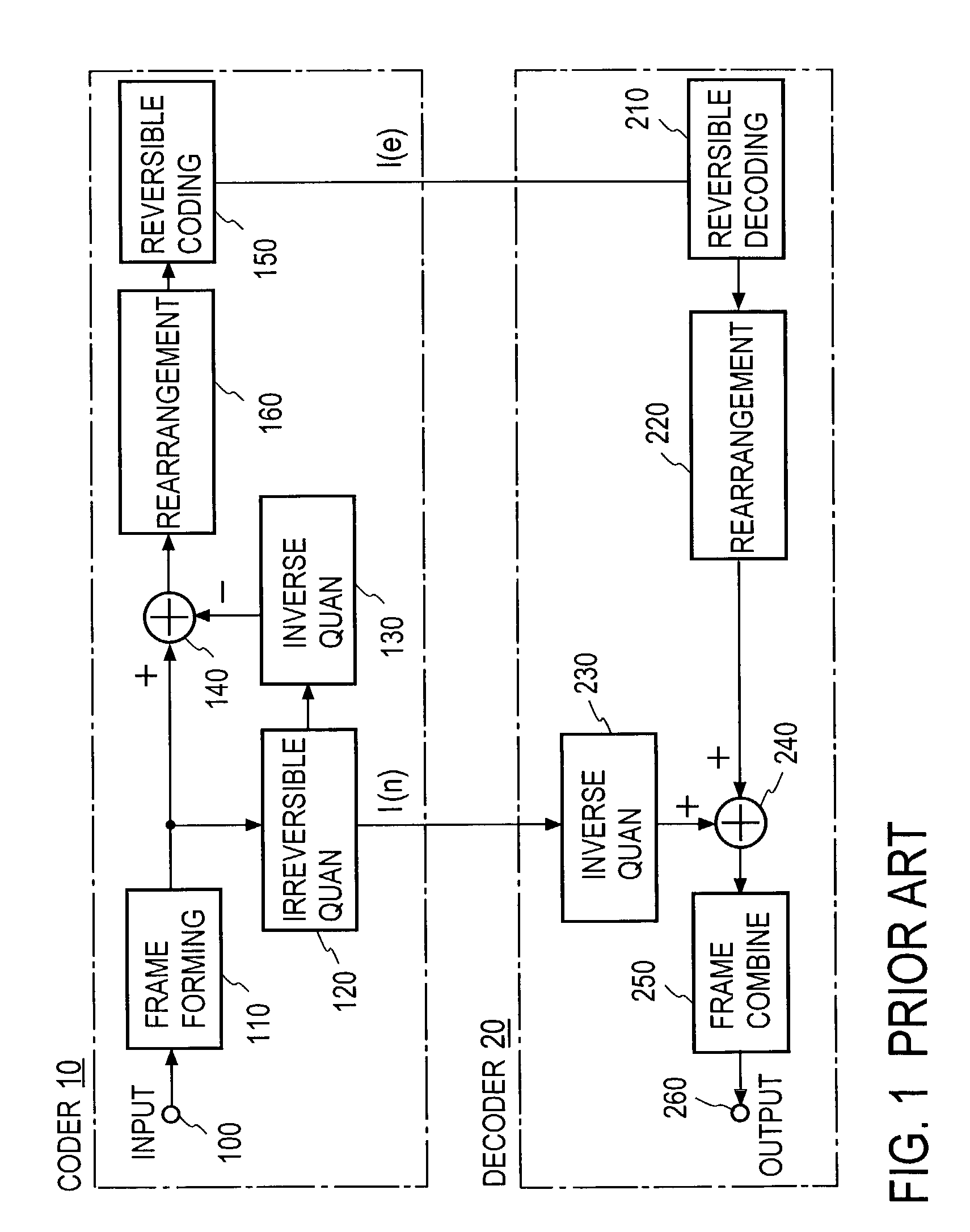
The conventional reversible compressing coding scheme presents a problem that when a bit erasure occurs during transmission, each sample to be reconstructed by the rearrangement part of the decoder 20 gets mixed with bits of other samples, seriously degrading the reconstructed signal quality.
This prior art scheme provides a compression ratio of approximately 1 / 2 at the highest and cannot achieve a 1 / 3 or 1 / 4 compression ratio with no substantial deterioration of quality nor can it implement compression with a satisfactory accuracy.
Moreover, even if the number of bits of the digital value representing the amplitude of the original signal is reduced by one bit, it is possible to restore the original waveform with the same accuracy as that with no bit reduction, but reducing four or more bits raises an auditory-sensation problem that high quantization noise is noticeable.

Method used


Image

  • Digital signal coding and decoding methods and apparatuses and programs therefor
  • Digital signal coding and decoding methods and apparatuses and programs therefor
  • Digital signal coding and decoding methods and apparatuses and programs therefor

Examples


embodiment 1

[0082]In FIG. 3 there are depicted in block form the coder 10 and the decoder 20 according to this embodiment of the present invention. This embodiment differs from the FIG. 1 prior art example in the provision of a header adding part 320, which sends out signals in a packet to reduce the influence of a bit error during transmission on the quality of reconstructed signal.

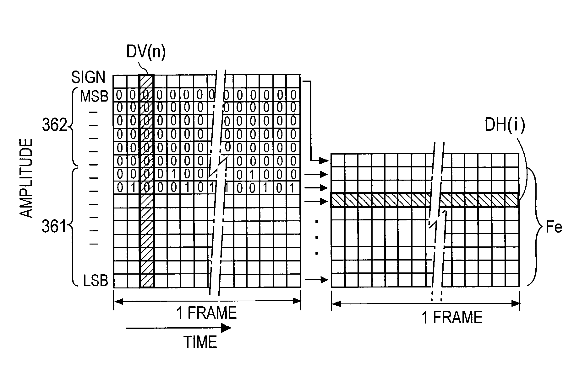
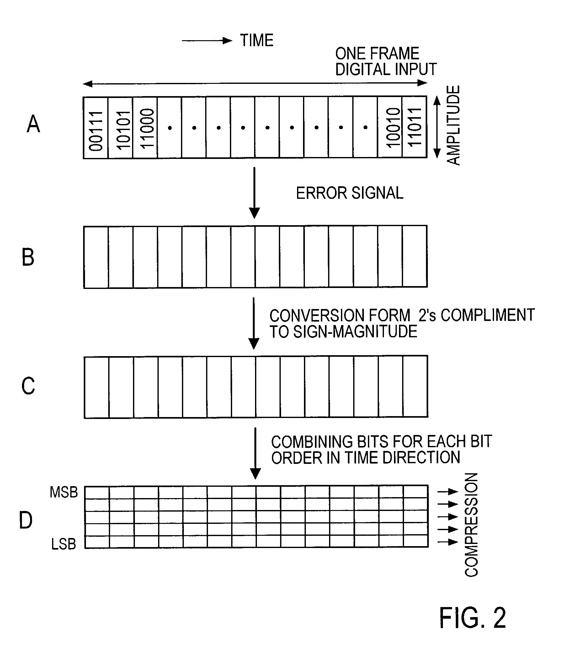
[0083]In the coder 10 an input signal sample sequence from an input terminal 100 is separated by a frame forming part 110 into frames each consisting of, for example, 1024 input signal samples (that is, n=samples at 1024 sample points), and in the rearrangement part 160 bits at each bit position in amplitude bit sequences of the respective samples are formed in the frame. In this case, the amplitude of the input signal sample sequence is represented by a positive or negative integer in the 2's complement format; it is preferable that, as is the case with the prior art, each sample represented in the 2's complement f...

embodiment 2

[0097]FIG. 6 illustrates in block form a second embodiment of the present invention. In the coder 10 the input signal sample sequence separated for each frame in the frame forming part 110 is provided to an auxiliary information generating part 350. The auxiliary information generating part 350 comprises a spectral envelope calculating part 351, a power calculating part 354 and an auxiliary information coding part 352. The input signal sample sequences separated in the frame forming part 110 for each frame are provided to the spectral envelope calculating part 351, wherein coefficients representing the spectral envelope are calculated, for example, as linear prediction coefficients LPC by linear predictive analysis, and in the power calculating part 354 the average power Pa of the input signal sample sequences for each frame is calculated.

[0098]Alternatively, the input signal sample sequences are input to an inverse filter 355 formed based on the linear prediction coefficients LPC, ...

embodiment 3

[0118]FIG. 11 illustrates in block form a third embodiment of the present invention applied to the coding scheme that is a combination of the high-compression-ratio irreversible coding described previously with reference to the FIG. 1 prior art example and the reversible compression of the error signal between the reconstructed signal and the original signal. As is the case with the FIG. 1 prior art example, in the coder 10 the digital input signal sequence from the input terminal 100 is irreversibly quantized in the high-compression-ratio irreversible quantization part 120, then the quantized information is inversely quantized (that is, decoded) in the inverse quantization part 130, then the difference between the inversely quantized signal (reconstructed signal) and the original digital input signal sequence from the input terminal 100 is calculated in the subtraction part 140, and the error signal that is the difference signal is applied to the frame forming part 110. That is, as...


PUM


Abstract

At the coder side, bits of samples of each frame of an input digital signal are concatenated every digit common to the samples across each frame to generate equi-order bit sequences, which are output as packets. At the decoding side, the input equi-order sequences are arranged inversely to their arrangement at the coder side to reconstruct sample sequences. When a packet dropout occurs, a missing information compensating part 430 correct the reconstructed sample sequences in a manner to reduce an error between the spectral envelope of the reconstructed sample sequence concerned and a known spectral envelope.

Description

BACKGROUND OF THE INVENTION[0001]The present invention relates to coding and decoding methods for reducing the number of bits that represent various digital signals such as an acoustic signal and an image signal and apparatuses and programs therefor, particularly, to those capable of controlling allowable distortion.[0002]To compress audio and visual information, there are proposed an irreversible distortion-prone or lossy coding scheme, and a distortion-free or lossless coding scheme. For irreversible compression coding (or lossy compression coding), there are several well known schemes such as ITU-T (International Telecommunications Union-Telecom Standardization) and ISO / IEC MPEG (International Organization for Standardization / International Electrotechnical Commission Moving Picture Experts Group) standard schemes. With these irreversible compression coding schemes, it is possible to compress the original digital signal down to 1 / 10 or less with a little loss of signal data. Howev...

Claims


Application Information

Patent Timeline
IPC IPC(8): G10L21/00G10L25/90H03M7/30H04N19/895
CPCH03M7/30G10L19/0017H04N19/895
Inventor MORIYA, TAKEHIROJIN, AKIOMORI, TAKESHIIKEDA, KAZUNAGA
Owner NIPPON TELEGRAPH & TELEPHONE CORP
Learn More