Magnetic liquid display panel

a technology of magnetic liquid and display panel, which is applied in the direction of static indicating devices, instruments, optics, etc., can solve the problems of complicated manufacturing process, small power consumption, and difficulty in producing large lcds, and achieve the effect of increasing responsivity

Inactive Publication Date: 2007-04-03
HONGIK UNIV IND ACAD COOP FOUND
View PDF8 Cites 3 Cited by
  • Summary
  • Abstract
  • Description
  • Claims
  • Application Information

AI Technical Summary

Benefits of technology

[0010]A first object of the present invention is to provide a display panel capable of providing moving pictures with an increased responsivity.
[0011]A second object of the present invention is to provide a magnetic display panel that can be easily manufactured at a low cost in large quantities because of the simplicity of its structure.
[0012]A third object of the present invention is to provide a magnetic display panel that is advantageous in constituting a super-large display device based on multiple integrations.

Problems solved by technology

LCDs, which are recently used for laptop computers, are representative of inactive luminescent display devices, are compact and light and consume a small amount of power.
Such LCDs have the above-mentioned merits, but also have the demerit that its manufacturing process is complicated due to the use of liquid crystal.
In addition, a complicated manufacturing process makes it difficult to produce large LCDs.
However, it is extremely difficult for the magnetic particles in the magnetic fluid used in such a conventional display panel have geometric anisotropy in a superfine state.
Also, light control based on the alignment or non-alignment of magnetic particles is not smooth.
In addition, the magnetic field coils 3 for applying a magnetic field to magnetic fluid must be formed in a multi-layered structure, thus requiring a very complicated manufacturing process.
However, this magnetic fluid display panel requires a strong magnetic field to move magnetic fluid, and accordingly requires high energy.
Also, the magnetic fluid display panel is very inferior in terms of pixel switching responsivity of the magnetic fluid, hence it is not suitable to form moving pictures.
In addition, since the magnetic fluid display panel adopts magnetic coils as a magnetic field forming unit, the miniaturization of cells, and mass-production are difficult, and the manufacturing costs are high.

Method used


Image

  • Magnetic liquid display panel
  • Magnetic liquid display panel
  • Magnetic liquid display panel

Examples


first embodiment

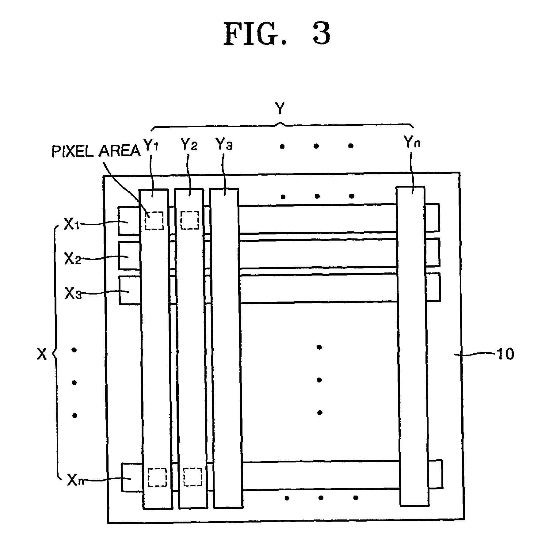
[0036]As described above, each of the pixel electrodes 30 may have a plurality of magnetic field producing units, for example, four magnetic field producing units 31a, 31b, 31a and 31b shown in FIGS. 4 and 5, but it may have a single magnetic field producing unit in some cases. According to the present invention, the number of magnetic field producing units for each pixel electrode 30 is not limited and can vary according to design conditions. Also, when a plurality of magnetic field producing units are provided for each of the pixel electrodes 30, they can be individually connected to the first and second electrodes X and Y. Alternatively, as described above, two adjacent magnetic field producing units 31a and 31b for one group are electrically connected to each other, and each group with both ends 32a and 32b can be connected to the first and second electrodes X and Y. A magnetic display panel according to the present invention will now be described, based on the structure in whic...

second embodiment

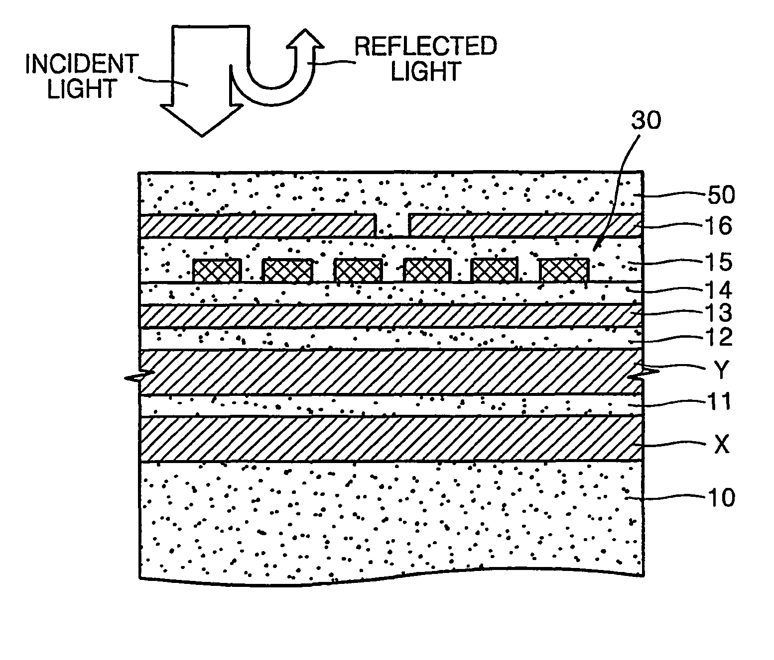
[0048]FIG. 10 is a partial cross-section of a stacked structure formed on a rear plate 10 in a magnetic display panel according to the present invention, in which a ferromagnetic film 18 for self memory is formed over the upper magnetic film 16. Referring to FIG. 10, first and second electrodes X and Y are formed on the rear plate 10, while a first insulating layer 11 sandwiches between the first and second electrodes X and Y. A second insulating layer is formed on the second electrode Y, and a lower magnetic film, that is, a magnetic shield layer 13, is formed of a soft or hard magnetic material on a second insulating layer 12.

[0049]A third insulating layer 14 is formed on the magnetic shield layer 13, and the magnetic field producing units 31a and 31b, which form a pixel electrode 30, are formed on the third insulating layer 14. A fourth insulating layer 15 is formed on a magnetic field producing unit 31a / 31b. An upper magnetic film 16 is formed of a hard or soft magnetic material...


PUM

PropertyMeasurementUnit
distanceaaaaaaaaaa
magnetic fieldaaaaaaaaaa
thicknessaaaaaaaaaa

Abstract

A magnetic display panel includes strips of first electrodes arranged in a first direction on an inner surface of a rear plate. Strips of second electrodes are arranged in a second direction, perpendicular to the first electrodes, and insulated from the first electrodes. Pixel electrodes are installed on each of the intersections of the first and second electrodes, and each has a spiral magnetic field producing unit electrically connected to the first and second electrodes. A magnetic film on the pixel electrodes has a magnetic gap through which a magnetic field produced by the pixel electrodes leaks. A magnetic fluid has a predetermined thickness on the inner surface of the rear plate. Such a display panel can provide moving pictures because of its improved responsivity, and, particularly, is easily fabricated at a low cost in large quantities because of its simple structure. Furthermore, the display panel is advantageous in building super-large display devices based on multiple integration.

Description

TECHNICAL FIELD[0001]The present invention relates to the field of magnetic liquid display panels, and more particularly, to a magnetic liquid display panel that has a high responsivity and is easily manufactured.BACKGROUND ART[0002]Display devices have been developed from cathode ray tubes (CRTs) using an accelerated electronic beam to plasma display panels (PDPs) based on plasma discharge, and liquid crystal displays (LCDs) using liquid crystal having an electro-optical effect. Besides, there are vacuum fluorescent displays (VFDs) using an electronic beam accelerated at a low speed, electro luminescent displays (ELDs), and magnetic liquid display panels. These display devices are classified into an active display device, which radiates light by itself, and an inactive luminescent display device, which requires a light source because the display device cannot emit light by itself.[0003]LCDs, which are recently used for laptop computers, are representative of inactive luminescent di...

Claims


Application Information

Patent Timeline
Patent Type & Authority Patents(United States)
IPC IPC(8): G09G3/34G02F1/09
CPCG02F1/091G02F2001/094G02F2201/123G02F1/094G02F1/09
Inventor SEO, JONG WOOK
Owner HONGIK UNIV IND ACAD COOP FOUND
Why Eureka
Try Eureka