
Lighting system and projector

Inactive Publication Date: 2007-03-20
SEIKO EPSON CORP
View PDF29 Cites 41 Cited by
  • Summary
  • Abstract
  • Description
  • Claims
  • Application Information

AI Technical Summary

Benefits of technology

[0008]In order to address or solve the above and / or other problems, the present invention provides a compact, thin, and lightweight lighting system having a high efficiency for light utilization and a simple structure. The invention also provides a compact, thin, and lightweight liquid crystal projector provided with the lighting system.
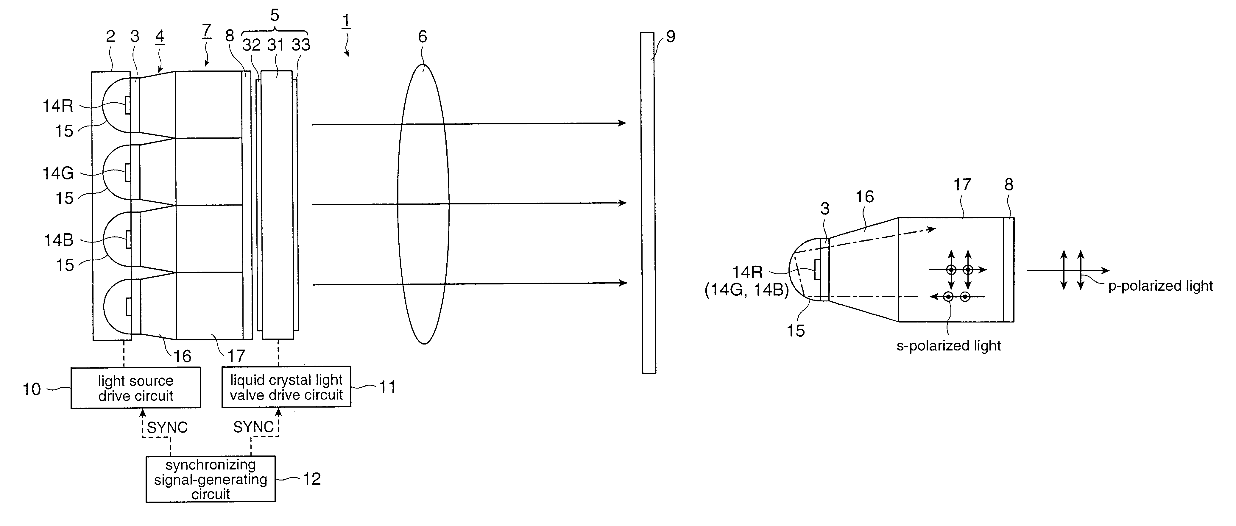
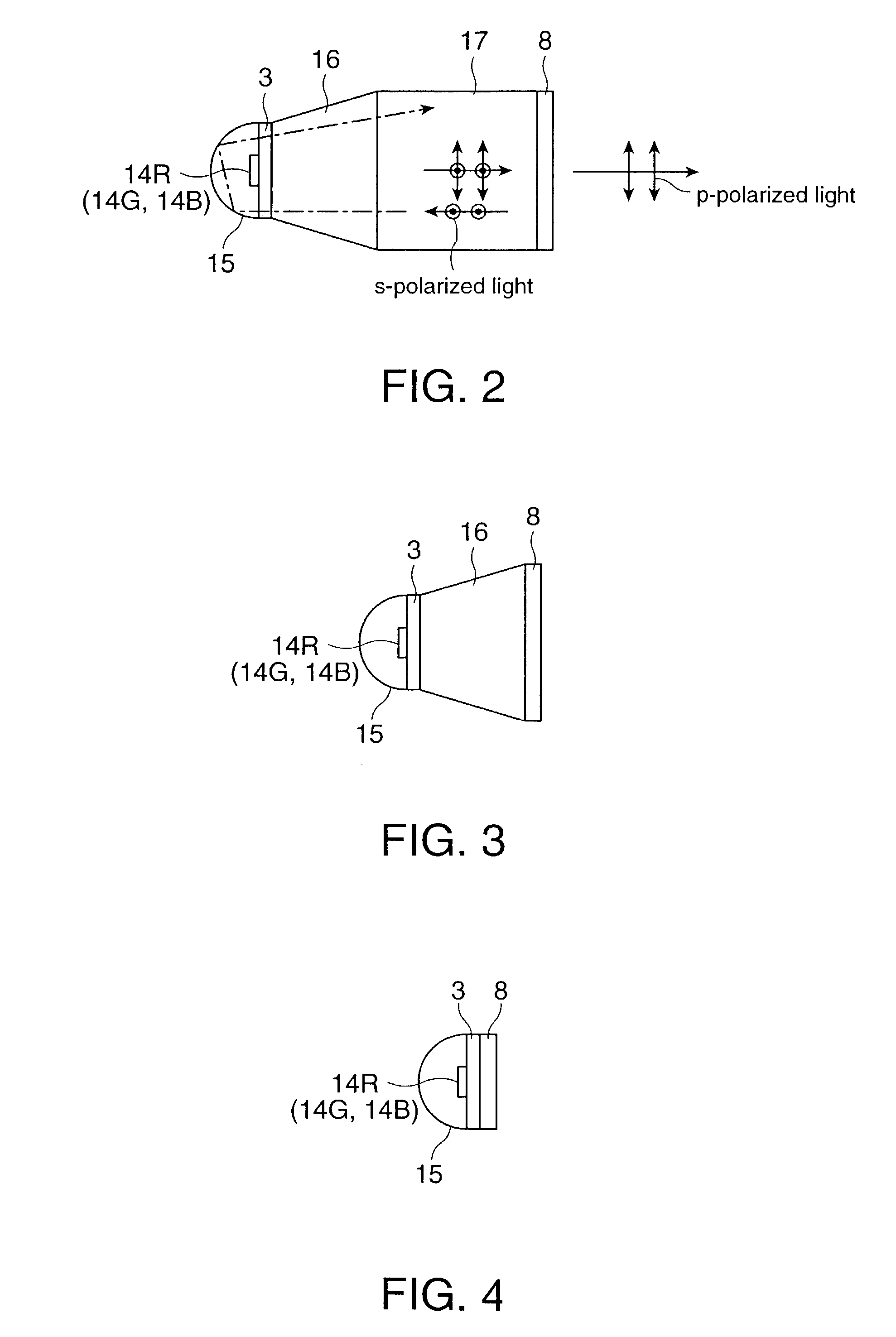
[0011]In the lighting system of the present invention, the reflective polarizing plate is used as an element having a polarization conversion function, in place of a related art PBS array. The reflective polarizing plate may be, for example, a multilayer polarizing film, which contributes to achievement of a compact, thin, and lightweight display, unlike the PBS array. The reflective polarizing plate can receive light on the entire surface, and does not require convergence of light to a specific position that is essential for the PBS array. Thus, the polarization conversion optical system needs no optical lens, resulting in a simplified structure. Furthermore, a wavelength plate, which is essential for the PBS array, is not required. Hence, the number of the component can be reduced.
[0013]According to this structure, in addition to a spontaneous change in polarization when the light is reflected by the reflective polarizing plate or the reflection plate, in this structure, the retardation film actively changes the polarization state. Hence, the change in the polarization is enhanced when the light reciprocally travels between the reflective polarizing plate and the reflection plate. As a result, the light transmittance of the reflective polarizing plate increases so that the efficiency for light utilization can be enhanced. Preferably, the retardation film has various phase differences at positions transmitting the light, rather than a uniform phase difference such as a half-wave or quarter-wave phase difference. According to this structure, the light reciprocally traveling between the reflective plate and the reflective polarizing plate is subjected to different types of phase modulation in the forward path and the backward path, resulting in an enhanced change in the polarization state.
[0017]In this structure, the reflective polarizing plate can be composed of an inorganic material, therefore having high light resistance and high heat resistance. Thus, this lighting system is particularly suitable for a projector that emits high-brightness light.
[0019]In this structure, the lighting system of the present invention contributes to achievement of a compact, thin, and lightweight projector, and enhances the efficiency for light utilization, resulting in higher brightness and lower electric power consumption. Furthermore, this projector employs a driving mode referred to as a “color field sequential system.” Thus, this projector requires only one light valve (single-plate structure), unlike related art three-plate projectors having three liquid crystal light valves for three color light beams. Accordingly, the projector requires only one illumination optical system for optical modulation device. Furthermore, the projector requires no color separation optical system and no color combining system, resulting in a significantly reduced number of the components, a simplified structure, and reduced cost.
[0021]Also, according to the projector of this structure, the lighting systems of the present invention contribute to achievement of a compact, thin, and lightweight projector, and enhance the efficiency for light utilization, resulting in higher brightness and lower electric power consumption. This projector requires a plurality of light valves, unlike the projector according to the first aspect. Since this projector emits different color light beams from the plurality of light sources and has the light valves for these color light beams, it does not require a color separation device, which is essential for any related art display. As a result, it has a simplified structure compared with the related art structure. Furthermore, synchronization of driving of the light sources with the light valves is not required, unlike the first aspect. Hence, the drive mechanism is simplified, and liquid crystal light valves having a lower response rate may be used.

Problems solved by technology

Unfortunately, the polarization conversion device having the PBS array of the related art projector is subject to the following problems.
Since each PBS element has a measure of area, the PBS array including PBS elements inevitably has a considerable size and does not meet recent requirements of reduction in the size, thickness, and weight of the projector or does not sufficiently meet these requirements.
Accordingly, the structure of the polarization conversion device is complicated.
In addition, the p-polarized light and the s-polarized light separated by the polarization beam separation film have different optical path lengths, resulting in shifting of the lighting condition on the light valve and thus a decrease in efficiency for light utilization.

Method used


Image

  • Lighting system and projector
  • Lighting system and projector
  • Lighting system and projector

Examples


first exemplary embodiment

[First Exemplary Embodiment]

[0028]A first exemplary embodiment of the present invention is described below with reference to FIGS. 1 to 5.

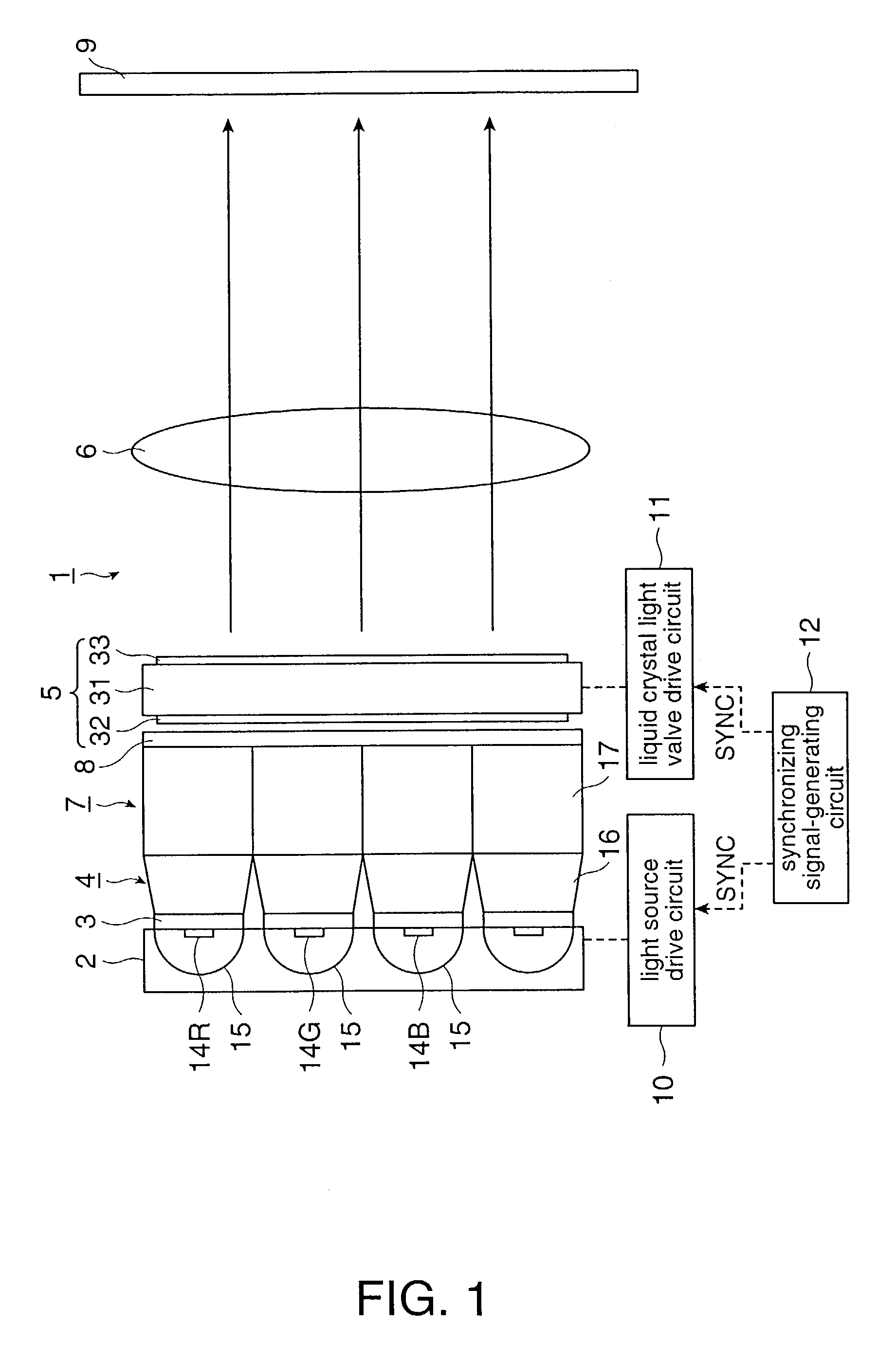
[0029]This exemplary embodiment describes a liquid crystal projector of a color field sequential system. FIG. 1 is a schematic of an overall configuration of the projector 1 that includes an LED array (light source) 2, retardation films 3, a taper rod lens array 4, a rod lens array 7, a reflective polarizing plate 8, a liquid crystal light valve 5 as a light modulation device, and a projection lens 6.

[0030]As shown in FIG. 1, the projector 1 of this exemplary embodiment includes the LED array 2 that has a plurality of light-emitting diodes (LEDs) 14R, 14G, and 14B emitting R light, G light, and B light, respectively, (only four LEDs are depicted for simplicity in FIG. 1); the retardation films 3 provided at the light emitting side of the LED array 2; the taper rod lens array 4 and the rod lens array 7 that uniform illumination intensities of color...

second exemplary embodiment

[Second Exemplary Embodiment]

[0044]A second exemplary embodiment of the present invention is described below with reference to FIG. 6.

[0045]This exemplary embodiment also shows a liquid crystal projector. While the first exemplary embodiment relates to a single-plate type of a color field sequential system, the second exemplary embodiment relates to a three-plates type. FIG. 6 is an enlarged schematic view of a projector. In FIG. 6, components having the same functions as in FIG. 1 are referred to with the same reference numerals, and a detailed description thereof has been omitted.

[0046]In the first exemplary embodiment, the LED array 2 having the LEDs 14R, 14G, and 14B that are arrayed in the same plane and emit R, G, and B different colors is used as a light source. In contrast, the liquid crystal projector 36 of this exemplary embodiment includes three planar light sources, i.e., an LED array 2R having LEDs 14R that are arranged in the same plane and emit red light, an LED array...


PUM


Abstract

The invention provides a compact, thin, and lightweight lighting system and projector. A lighting system included in a projector according to the present invention is provided with an LED array having LEDs and a reflective plate at the rear side of the LEDs in the light emitting direction, retardation films, a taper rod lens array, a rod lens array, and a reflective polarizing plate.

Description

BACKGROUND OF THE INVENTION[0001]1. Field of Invention[0002]The present invention relates to a lighting system and a projector. Particularly, the invention relates to a structure of a lighting system having a high efficiency for light utilization.[0003]2. Description of Related Art[0004]A related art projector combines imaging light with a light modulation unit, such as a liquid crystal light valve, and projects the combined and enlarged light image on a screen from a projection optical system including a projection lens. In a lighting optical system used in such a projector, light emerging from a light source, such as a metal halide lamp, is randomly polarized light. However, a liquid crystal projector including a liquid crystal light valve using polarized light utilizes only polarized light in one direction for display. When light from the light source is incident on the liquid crystal light valve, merely a half quantity of light is absorbed in a polarizing plate at the light inci...

Claims


Application Information

Patent Timeline
IPC IPC(8): F21V9/14G02F1/13G02B27/28G02F1/1335G02F1/13363G03B21/00G09F19/12G09F19/18H04N5/74H04N9/31
CPCH04N5/74H04N9/3197H04N9/3167H04N9/315
Inventor SAKATA, HIDEFUMITAKEDA, TAKASHI
Owner SEIKO EPSON CORP
Learn More