
Mixing valve mounting assembly

a technology for mounting assemblies and mixing valves, which is applied in the direction of machine supports, transportation and packaging, and other domestic objects, etc., can solve the problems of time-consuming, difficult, and expensive problems of replacing old mixing valves

Inactive Publication Date: 2007-03-20
BRUNO JAMES
View PDF11 Cites 37 Cited by
  • Summary
  • Abstract
  • Description
  • Claims
  • Application Information

AI Technical Summary

Problems solved by technology

Consequently, installing a mixing valve in a shower typically requires constructing a wooden frame to support the valve.
Because mixing valves are not sold with mounting brackets, replacing an old mixing valve can be difficult, time consuming and expensive.

Method used


Image

  • Mixing valve mounting assembly
  • Mixing valve mounting assembly
  • Mixing valve mounting assembly

Examples


Embodiment Construction

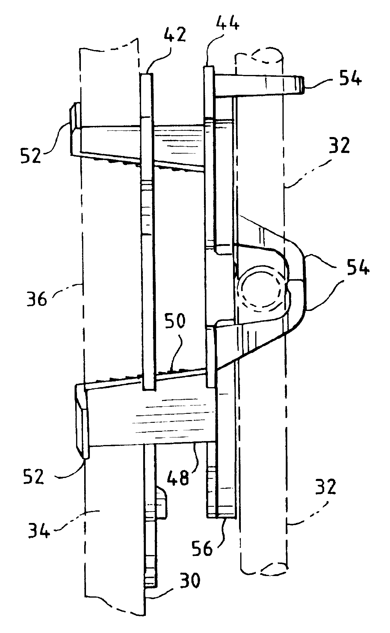
[0024]The invention will now be described in terms of an assembly for mounting a mixing valve onto a fiberglass shower stall wall. It should be understood, however, that the invention also may be used with tub and shower stalls, and that the shower stall need not be fiberglass, but could be vinyl, metal, or any other suitable material of construction. Finally, it should be noted that the dimensions given in this specification are approximations and given for illustrative purposes only, and that the invention is not to be limited to any particular dimensions.

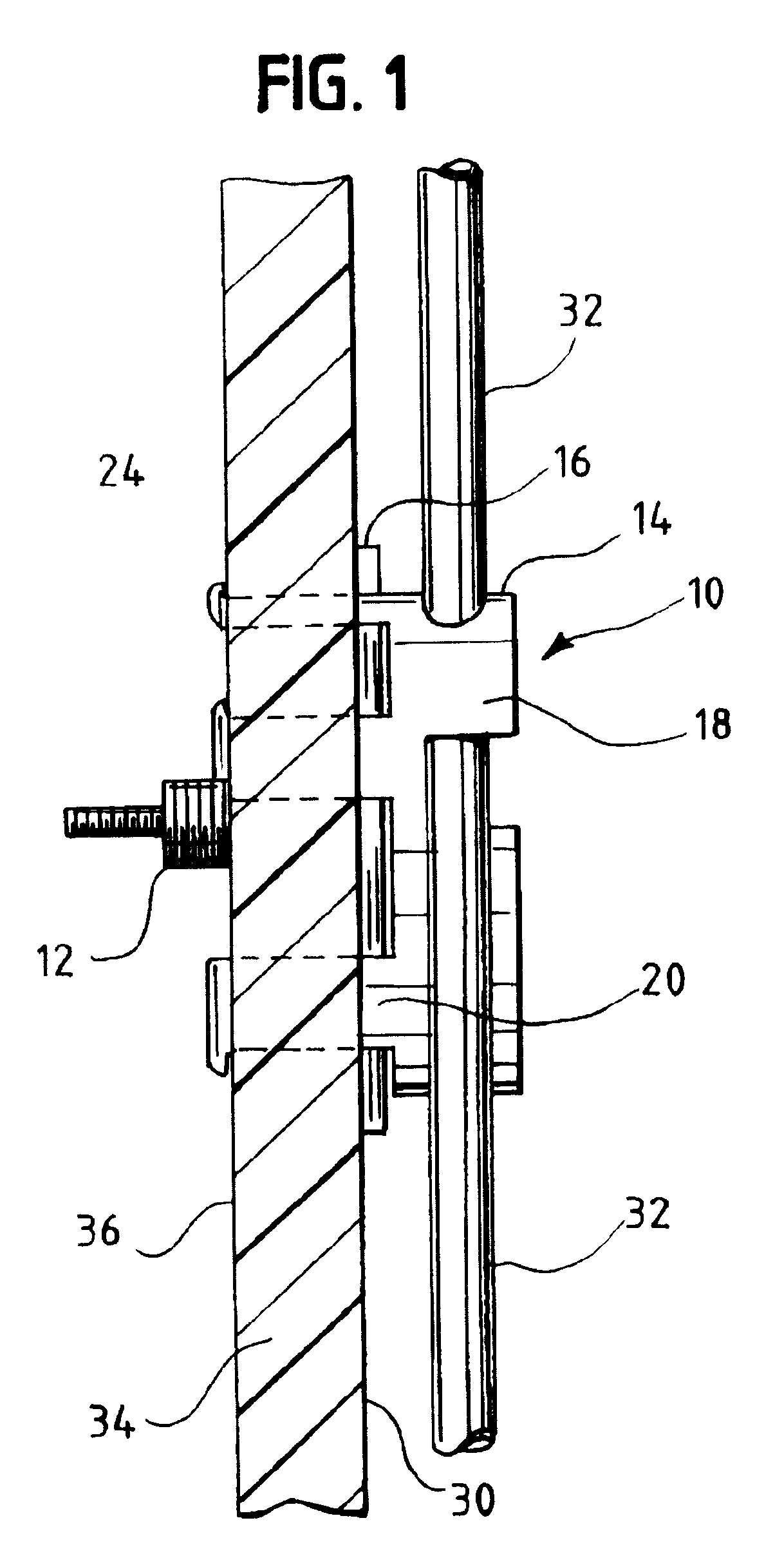
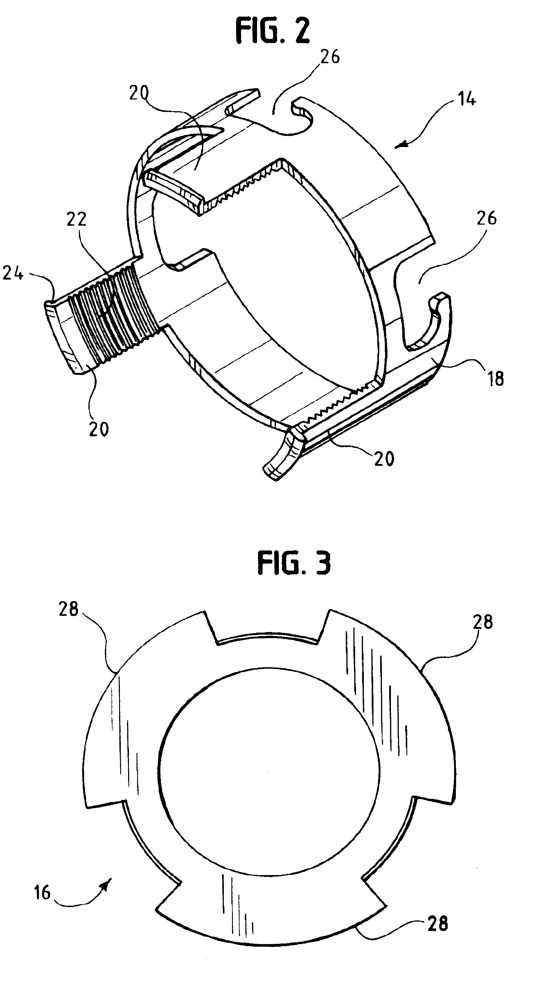
[0025]Turning to the drawings, there is shown in FIG. 1 one embodiment of the present invention, a mounting assembly 10 for a mixing valve 12, shown in side view installed onto a shower stall wall 34. The assembly 10 comprises a valve mounting sleeve 14 and a locking plate 16, and may be used to mount a mixing valve 12 directly to the wall of a fiberglass shower stall.

[0026]As best shown in FIG. 2, the valve mounting sleeve 14 co...


PUM


Abstract

An assembly for mounting a tub / shower mixing valve onto a fiberglass shower stall wall. The assembly comprises a valve mounting sleeve and a locking plate that helps secure the mounting sleeve to the shower stall wall. Alternatively, the mounting sleeve may be secured to the shower stall wall by bolts threadably connected to the mounting sleeve.

Description

BACKGROUND OF INVENTION[0001]This patent relates to a mounting assembly for a tub / shower mixing valve. More particularly, this patent relates to an assembly for mounting a tub / shower mixing valve directly to a fiberglass shower wall.[0002]Single handle mixing valves are used in place of two handle valves to mix hot and cold water before use in a shower, tub or basin. Single handle mixing valves typically are made of brass and have four ports, one each for the hot and cold water inlets, one for the shower pipe and one for the tub spout pipe. If the installation is for a shower only, then the tub filler port is capped.[0003]Single handle mixing valves are not sold with any type of mounting bracket. Consequently, installing a mixing valve in a shower typically requires constructing a wooden frame to support the valve. The valve can be mounted directly to vertical wall studs or it can be supported between two studs by mounting it to a horizontal board placed between the studs. After the...

Claims


Application Information

Patent Timeline
IPC IPC(8): F16L5/00E03C1/042
CPCE03C1/042Y10T137/6851Y10T137/698Y10T137/6969
Inventor HODGES, B. EUGENE
Owner BRUNO JAMES
Learn More