Air conditioning system with moisture control

a technology of air conditioning system and humidity control, which is applied in the direction of temperatue control, dynamo-electric motor/converter stopper, starter details, etc., can solve the problems of toxic mold, poor ventilation of indoor spaces, and accumulation of contaminants in the interior air, so as to accelerate dehumidification and prevent the buildup of humidity levels. , the effect of reducing the buildup of contaminants

Active Publication Date: 2007-03-20
CURTIS MORTON
View PDF14 Cites 41 Cited by
  • Summary
  • Abstract
  • Description
  • Claims
  • Application Information

AI Technical Summary

Benefits of technology

[0017]It is an object of the present invention to accelerate dehumidification during a normal air conditioning cycle to prevent buildup of humidity levels within a home, or other structure, that the air conditioning system cannot easily remove.
[0018]It is also an object of the invention to provide an effective

Problems solved by technology

There are some concerns that poorly ventilated indoor spaces permit contaminants in the interior air to become concentrated as the air is recirculated.
One part of this perceived problem is that of toxic mold.
The problems related to poor indoor air quality may be increased in newer homes, which have sought to become more energy efficient.
However, these measures also lead to more “stale air” in the home and may exacerbate indoor air quality problems.
As a result, moisture is not effectively removed from the air.
If the air conditioning cycle is short, it does not effectively remove the humidity.
Unfortunately, these techniques are expensive and largely ineffective.
These “variable speed furnaces” require a specialized D/C motor, are quite expensive as are replacement motors for them.
The variable speed furnaces have additional features that can create problems if not accommodated in the design of the air conditioning system.
Additionally, it is pointed out that these variable speed units are

Method used


Image

  • Air conditioning system with moisture control
  • Air conditioning system with moisture control
  • Air conditioning system with moisture control

Examples


Embodiment Construction

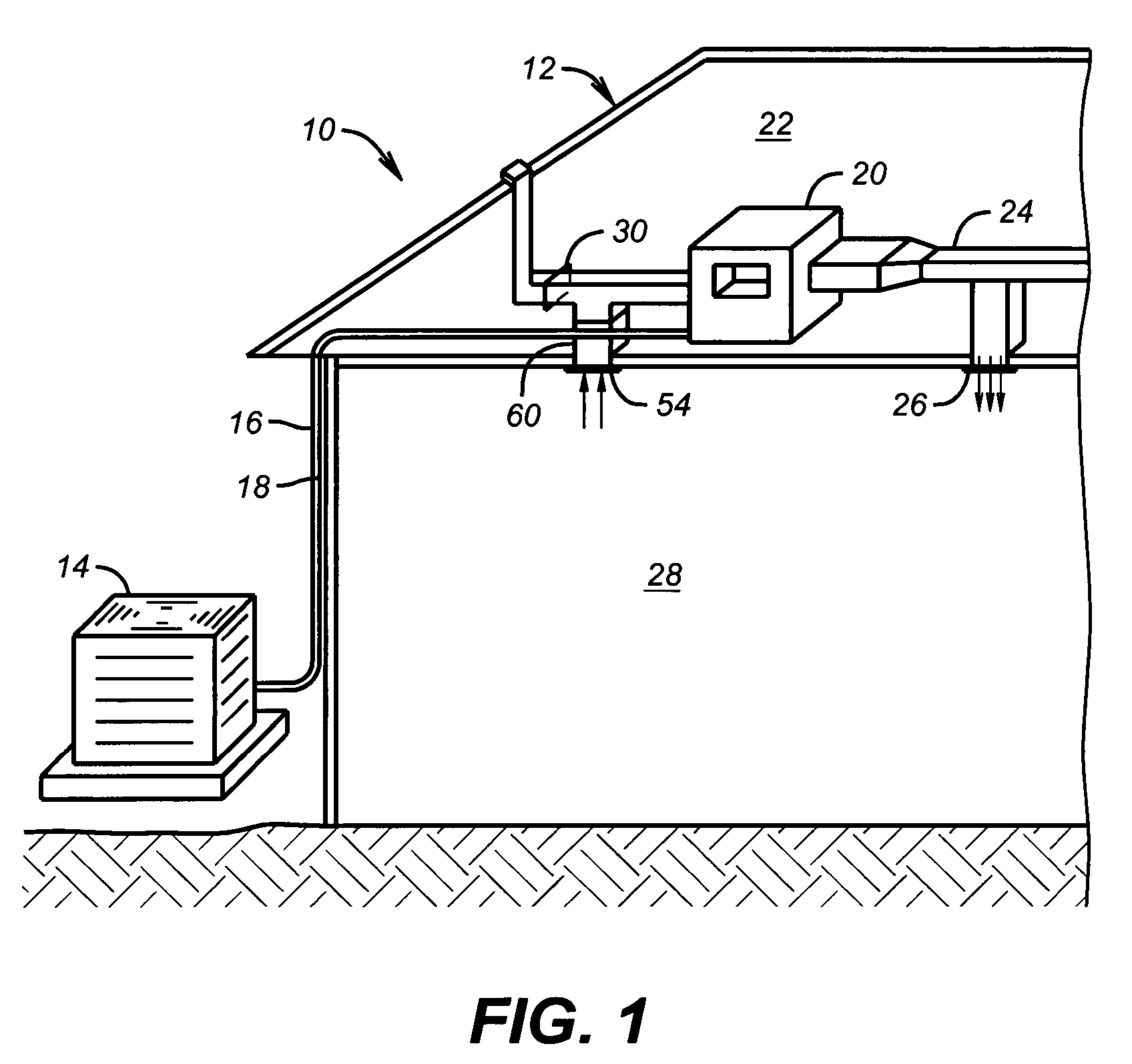
[0024]Referring first to FIG. 1, there is shown an exemplary air conditioning system 10 that is used for cooling of a home 12. The air conditioning system 10 includes a condensing unit 14 that is located outside of the home 12. Fluid conduits 16, 18 interconnect the condensing unit 14 with a furnace / air handler / evaporator unit 20 that is located in the attic space 22 of the home 12. Ductwork 24 extends from the furnace / air handler / evaporator 20 to a number of vents 26 (one shown) that permit conditioned air to flow into the occupied portions 28 of the home 12. A motorized outside air damper 30 is incorporated into the return air ductwork 60. The air damper 30 is a known device that may be selectively opened and closed to admit outside air into the return air ductwork 60.

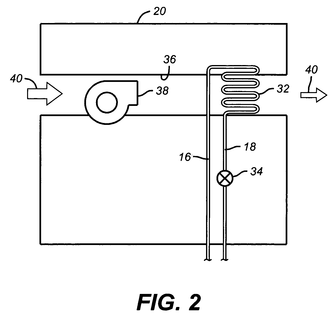
[0025]FIG. 2 is a schematic illustration of components associated primarily with the furnace / air handler / evaporator unit 20 of the air conditioning system 10. As may be seen, the furnace / air handler / evaporator 20 inc...


PUM


Abstract

Devices and methods for moisture removal from conditioned air. A speed control is provided that selectively operates the blower motor of an air conditioning system at a lower speed. The speed control may include a time delay circuit and single pole, double throw relay. The speed control is used to slow the speed of the air cycler during the initial stage of a cooling cycle. This initial stage is typically the first 5–7 minutes of the air conditioning cycle. In a further aspect, a humidistat is operably associated with the system for detection of humidity levels within the air of a home or other structure. The system is programmed to close the motorized outside air damper in the event that humidity levels exceed a predetermined level, thereby limiting further entry of humid outside air into the home.

Description

[0001]This application claims the priority of U.S. provisional patent application Ser. No. 60 / 420,523 filed on Oct. 23, 2002.BACKGROUND OF THE INVENTION[0002]1. Field of the Invention[0003]The invention relates generally to air conditioning systems and, in particular aspects, to devices and methods for controlling humidity during air conditioning cycles.[0004]2. Description of the Related Art[0005]Indoor air quality has become a significant concern, particularly for homes, but also for office buildings where workers spend much of their day. There are some concerns that poorly ventilated indoor spaces permit contaminants in the interior air to become concentrated as the air is recirculated. One part of this perceived problem is that of toxic mold.[0006]Air conditioning serves two basic purposes. The first is the removal of heat from the air within the home or other structure. The second function is the removal of moisture, or humidity, in the air. In order to effectively remove humid...

Claims


Application Information

Patent Timeline
IPC IPC(8): F25D17/04G05B5/00B60H1/00F24F3/14F24F11/00
CPCB60H1/00785F24F3/14F24F11/0079F24F11/0008Y02B30/746F24F11/0015F24F11/30F24F2110/20F24F11/77Y02B30/70F24F11/88
Inventor CURTIS, MORTON
Owner CURTIS MORTON
Why Eureka
Try Eureka