
Walk reel mower

a mower and reel technology, applied in the direction of agriculture tools and machines, propulsion using engine-driven generators, transportation and packaging, etc., can solve the problems of jerk or discontinuity, jerk or discontinuity felt by the operator in the handle as the operator pushes down on the handle to raise the cutting unit, and disadvantages of the chain support uni

Inactive Publication Date: 2007-03-20
TORO CO THE
View PDF18 Cites 28 Cited by
  • Summary
  • Abstract
  • Description
  • Claims
  • Application Information

AI Technical Summary

Benefits of technology

The design enhances ground contour following, reduces scalping and scuffing, simplifies control operations, prevents lubricant leakage, and maintains consistent cutting performance regardless of reel wear, improving overall operational efficiency and user experience.

Problems solved by technology

This is undesirable.
While the ground contour following characteristics of a reel mower are not possessed by a reel mower with a cutting unit that is rigid with the frame, the use of chains to support the cutting unit provides disadvantages of its own.
Thus, when pushing down on the handle to lift the cutting unit off the ground, the operator first feels a smooth motion while the chains tighten and then feels a jerk or discontinuity when the operator suddenly has to push down harder to get the cutting unit to come up.
The jerk or discontinuity felt by the operator in the handle as the operator pushes down on the handle to raise the cutting unit is a disadvantage.
This is simply not possible with cutting units suspended by chains that must be tightened before the cutting unit rises.
While this provides a ground contour following ability without using slack chains to support the cutting unit, pushing down on the handle assembly will not lift the cutting unit off the ground.
Thus, the mower shown in the Speiser patent is much more difficult to maneuver than the reel mowers described earlier.
In addition, the cutting unit shown in the Speiser patent is not itself totally self-supporting on the ground, but relies on the traction wheels of the mower frame in conjunction with a roller on the cutting unit for proper ground engaging support.
As a result, the fore-and-aft wheelbase of the mower is relatively large.
If the bump is small enough, the traction wheels may clear the bump before the cutting reel / bedknife interface reaches the high spot of the bump, thus still resulting in scalping.
Another problem with prior art walk reel mowers is the nature of the drives or transmissions used to power the traction drive and the cutting reel.
The use of two gearboxes increases expense as well as requiring sufficient space on the mower frame for housing both gearboxes.
In addition, the use of two gearboxes gives the mower a cluttered appearance.
In this location, it was difficult to keep the differential sealed and lubricated, and repair or replacement of the differential was also difficult.
Moreover, any leakage of the lubricant from the differential out of the traction drum is problematic as such a lubricant can easily kill or mar the grass or turf being cut by the mower.
Despite the attempt at simplification shown in the Jerram patent, various deficiencies are still present.
This gives rise to the lubricating and lubricant leakage problems discussed above.
In addition, the overall drive and differential systems disclosed in Jerram involve the use of a large number of components, which leads again to increased cost.
It is a problem with such a drive in keeping the belt taut as the cutting unit and mower frame move relative to one another.
In addition, flexing or twisting of the drive belt is quite hard on the belt leading to relatively short belt life.
Again, having to lubricate a flexible drive shaft to the cutting reel is a problem because such a flexible drive shaft is generally exposed and located above the cutting reel.
Thus, the lubricant for the drive shaft or the universal joints at either end can leak and drop down onto the grass or turf, thus damaging the grass or turf.
As in the case with leakage of the lubricant from a drum carried differential, this is not desirable.
This prior art control system is disadvantageous as it is relatively cumbersome to start and stop the cutting reel.
This back and forth walking motion is obviously inconvenient and tiring to do.
As a result, the operator tends to leave the cutting reel in operation even at times when the cutting reel should otherwise be shut off.
As such, the controls can be somewhat confusing to use as the operator must remember which control operates which item.
Moreover, the use of separate controls again unduly clutters the handle assembly.
If the basket is partially filled with grass clippings, this can be difficult to do.
Even if it can be done, it is inconvenient for the operator to have to reattach the grass basket.
This change in the quality of the cutting is not desirable.

Method used


Image

  • Walk reel mower
  • Walk reel mower
  • Walk reel mower

Examples


Embodiment Construction

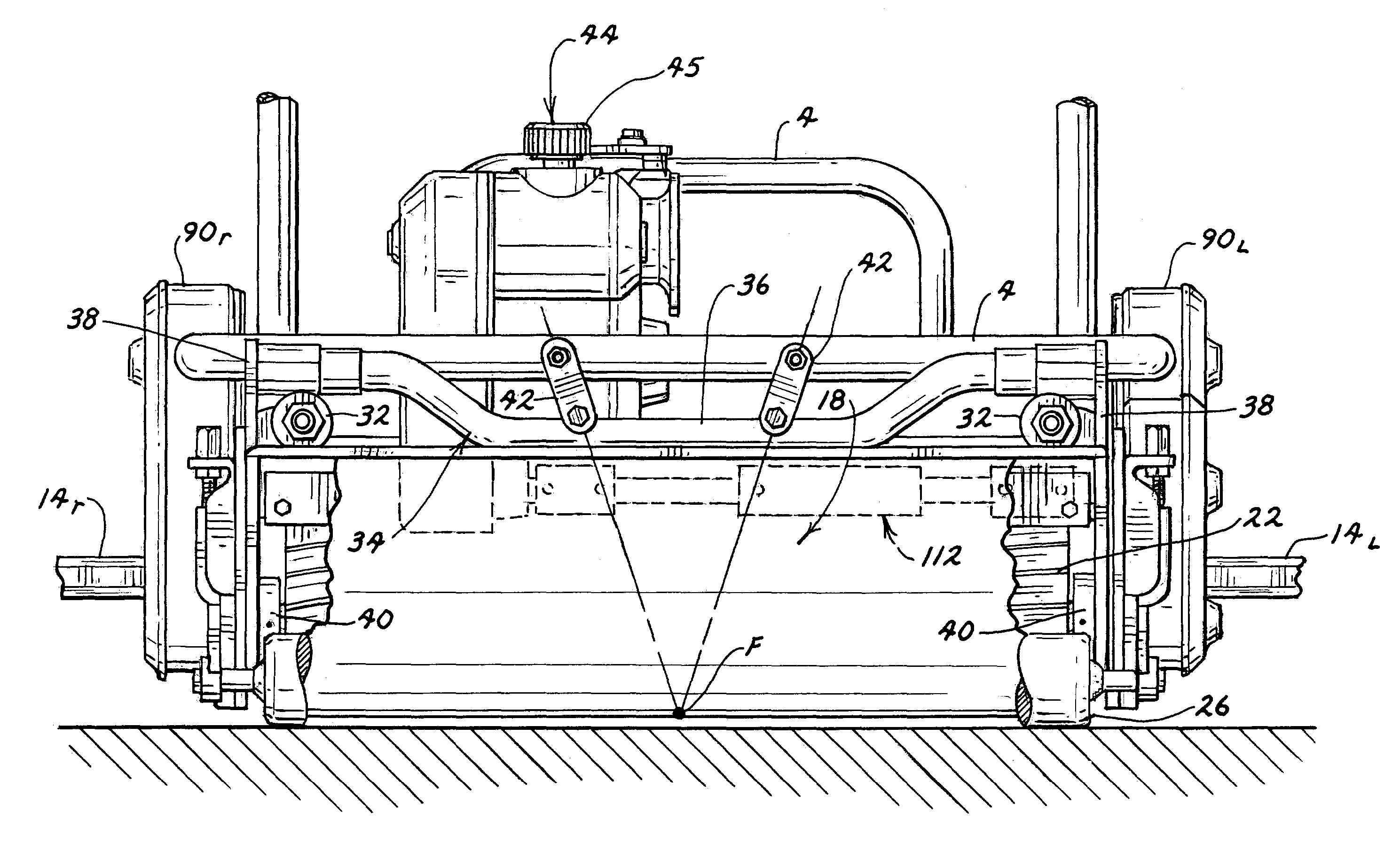
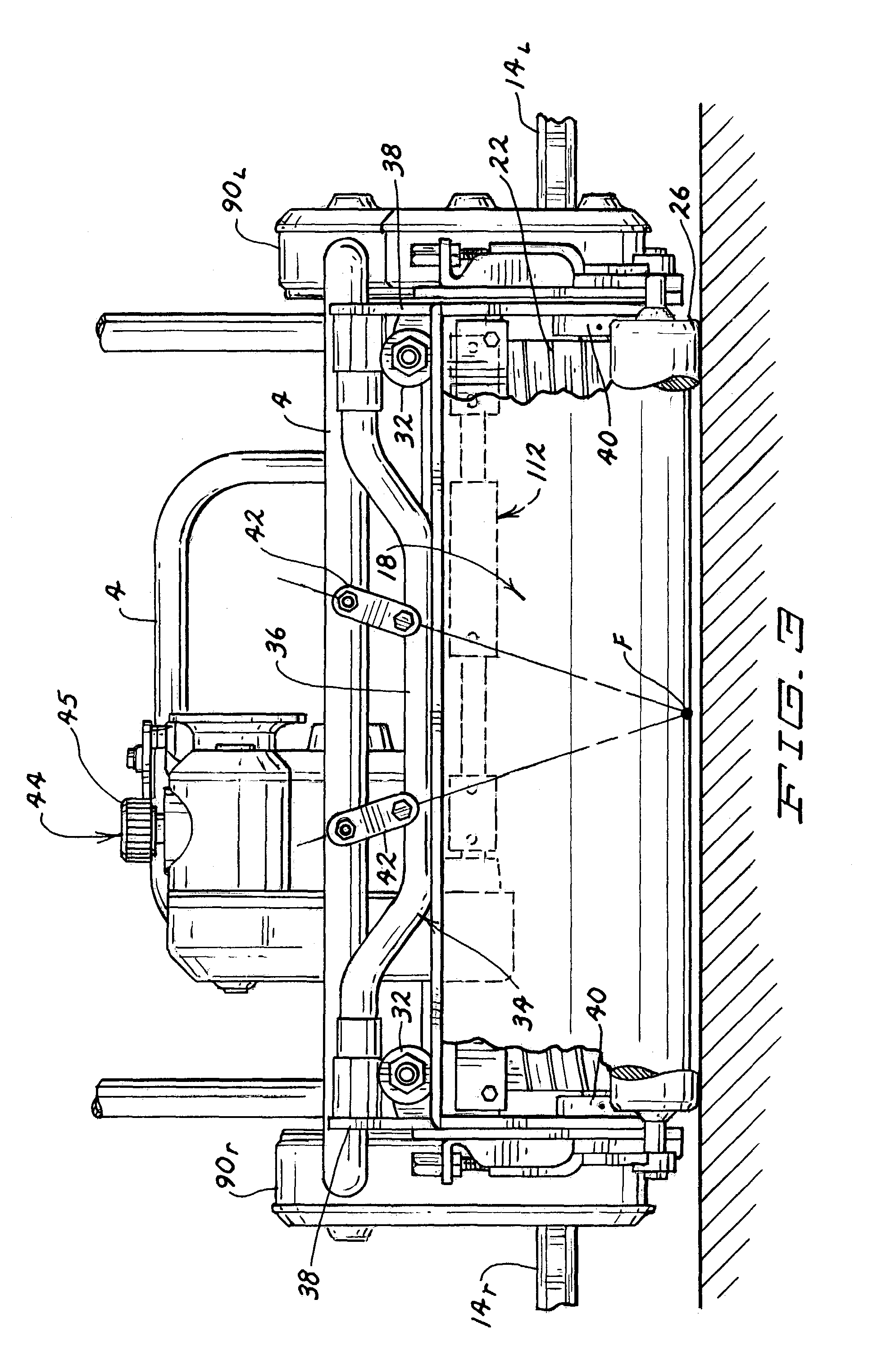
[0052]This invention relates to a walk reel mower 2 having a reel cutting unit for cutting grass. The term “walk reel mower” is used in this application to refer to a walk reel mower 2 in which the operator walks behind walk reel mower 2 as walk reel mower 2 is operated. The operator is not supported or carried by walk reel mower 2 as would be the case with a riding reel mower. More particularly, walk reel mower 2 is suited for mowing grass at low heights of cut where precision cutting is required, such as on the greens of a golf course. However, the various aspects of the invention disclosed herein are not limited for use on a walk reel mower for mowing only golf greens, but can be used on walk reel mowers for mowing other turf areas as well.

The Overall Walk Reel Mower

[0053]FIG. 1 provides an overall view of one embodiment of a walk reel mower 2 according to this invention. Walk reel mower 2 includes a frame 4 on which a power source 6, such as an internal combustion engine, is car...


PUM


Abstract

A walk reel mower includes a pair of inclined rigid links for mounting the reel cutting unit to the reel mower frame for rolling about a longitudinal axis, and a pair of vertical support arms for mounting the reel cutting unit to the reel mower frame for pitching about a transverse axis. An integrated gearbox houses both the traction and reel drives, including the differential that is part of the traction drive, as well as a parking brake. A flexible drive shaft powers the cutting reel from the gearbox and is made from materials that do not require petroleum based lubricants to avoid the possibility of damage to the turf or grass. A single control handle located on the handle of the mower actuates both the reel and traction drives. The reel cutting unit includes a back plate which has a portion formed as a hollow beam for strength. The reel cutting unit also has a pivot axis for the bedknife allowing adjustment of the bedknife relative to the cutting reel without changing the longitudinal location of the front edge of the bed-knife to ensure consistent cutting of the cutting unit. Finally, an improved mounting for the grass basket used on the cutting unit is disclosed which mounting avoids in advertent disengagement of the grass basket from the cutting unit.

Description

CROSS REFERENCE TO RELATED APPLICATIONS [0001]This application is a division of application number 09 / 892,194, filed Jun. 26, 2001, U.S. Pat. 6,622,464, which claims the benefit of provisional application number 60 / 214,133 filed Jun. 26, 2000TECHNICAL FIELD [0002]This invention relates to a walk reel mower having a reel cutting unit that “floats” relative to the reel mower frame to allow the reel cutting unit to conform to the ground contours to avoid scalping and / or scuffing of the turf being cut. In addition, this invention relates to a gearbox that integrates the traction and reel drives of the reel mower, to a self-lubricating drive shaft that transfers drive to the cutting reel, to a single control handle for operating both the traction and reel drives, to an improved mounting on the reel mower frame for supporting the grass collecting basket, to an improved pivotal mounting for the bedknife, and to an improved back plate construction for the reel cutting unit.BACKGROUND OF TH...

Claims


Application Information

Patent Timeline
Patent Type & Authority Patents(United States)
IPC IPC(8): A01D34/53A01D34/47A01D34/62
CPCA01D34/47A01D34/62B60L11/14A01D2101/00B60L2270/145B60L2240/12B60L2240/421B60L2250/24B60L2200/40B60L50/16Y02T10/64Y02T10/7072Y02T10/70
Inventor GOMAN, GERALD E.PATTON, ROBERT D.SCHNOTALA, DONALD B.
Owner TORO CO THE
Learn More