
Ultrasonically welded, staked or swaged components in an implantable medical device

Inactive Publication Date: 2007-03-06
MEDTRONIC INC
View PDF33 Cites 62 Cited by
  • Summary
  • Abstract
  • Description
  • Claims
  • Application Information

AI Technical Summary

Benefits of technology

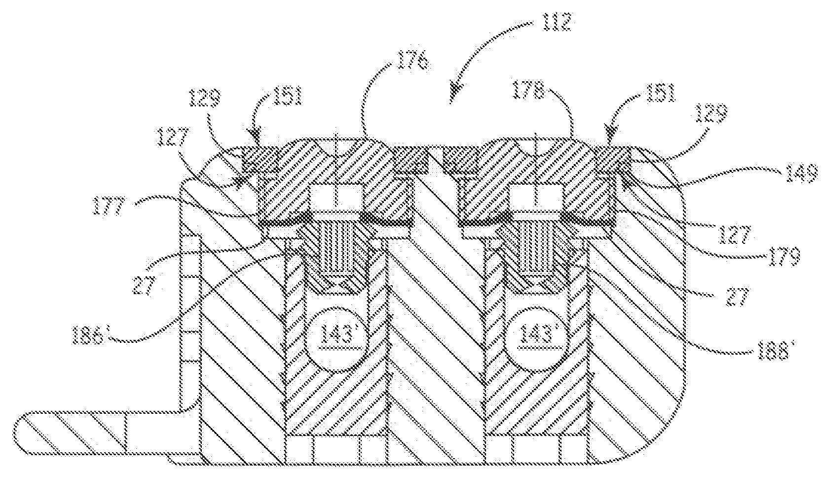
[0028]An advantage of the present invention relates to the inherent modular configuration of the assembled parts. That is, for header modules having multiple connector ports, a like number of grommets, lids and, optionally, sleeve-type mechanical stop members may be used. Furthermore, such modularity allows one assembly sequence for a variety of header configurations.
[0029]As will be appreciated with reference to the drawings, and particularly in the case of the grommet assembly, a central portion of reduced thickness may be used to assist a user manually align the instrument adjustment tool and to provide slightly less insertion resistance. In addition, both the grommet and septum member preferably have a peripheral shoulder portion that corresponds to structure of the lid or cover. Also, as noted above, to reduce or eliminate post fabrication rework of the components due to excess material (e.g., “flash”), a channel or slot may be formed at the surface of and adjacent to the bonded components to receive excess material.
[0030]A fluid tight seal at the junction of the lid or cover and the periphery of the recess and / or between the grommet or septum and the wall of the recess is preferably aided by placing the grommet or septum under compression during fabrication. That is, the grommet or septum expands after fabrication to help form the fluid seal. Additional features or components, such as a mechanical stop or substantially non-compressible ring of material, may be disposed within the recess. Such a mechanical stop may comprise a perforated disk, with such perforation adapted to admit the tip of a syringe, for certain drug pump applications.
[0031]In a preferred embodiment wherein a setscrew is disposed in the recess, said setscrew is a “dog tip” type setscrew (i.e., a partially threaded shank). When such a dog tip screw is rotated counterclockwise, it remains partially inserted in a threaded bore. A halt ring coupled between the setscrew and the compressible grommet helps ensure that the screw cannot be reversed too far and thus cannot reversed through the grommet and will neither further compress the grommet nor force the lid away from the IMD.
[0032]The foregoing and other objects, advantages and features of the present invention will be appreciated better by referring to the appended claims, drawings and detailed description.

Problems solved by technology

Such early implantable cardiac pacemakers suffered very short useful lives due to moisture ingress through the epoxy and causing electrical dendritic growth across, and shorting of, adjacent points of the circuit, battery terminals, or discrete transistor terminals.
In addition, pacing leads frequently failed due to conductor stress fractures, and batteries depleted prematurely for a variety of reasons.
This approach is time consuming and not terribly precise.
If the resulting connector header assembly fails to meet dimensional tolerances or other quality requirements, it is difficult to rework the IPG.
Any substantial initial or time-induced misalignment of the lead connector receptacle bores extending through the molded module housing and the connector block bores can make initial attachment or removal and replacement of a lead connector end impossible or unreliable.
While the approaches described in those patents have merit, they require the use of additional precision piece parts and assembly steps that may add to the cost and time required to assemble the connector header module and connect it to the hermetically sealed enclosure.
The use of silicone rubber presents certain difficulties and disadvantages, however, most of which relate to dimensional instability and lack of rigidity, lack of an aesthetically pleasing physical appearance and potential discoloration of the silicone rubber during storage and sterilization.
Furthermore, periodic replenishment of the fluid reservoir of such pumps typically requires a resilient septum member through which said fluid is injected.
Multi-step wax removal processes were used in which detergents and solvents were applied and removed, thereby adding incremental costs and additional time to the IMD manufacturing process.
Such removal processes were typically temporary.
In addition, medical grade adhesive typically requires several hours to adequately cure, further reducing the interval in which an IMD may be manufactured.

Method used


Image

  • Ultrasonically welded, staked or swaged components in an implantable medical device
  • Ultrasonically welded, staked or swaged components in an implantable medical device
  • Ultrasonically welded, staked or swaged components in an implantable medical device

Examples


Embodiment Construction

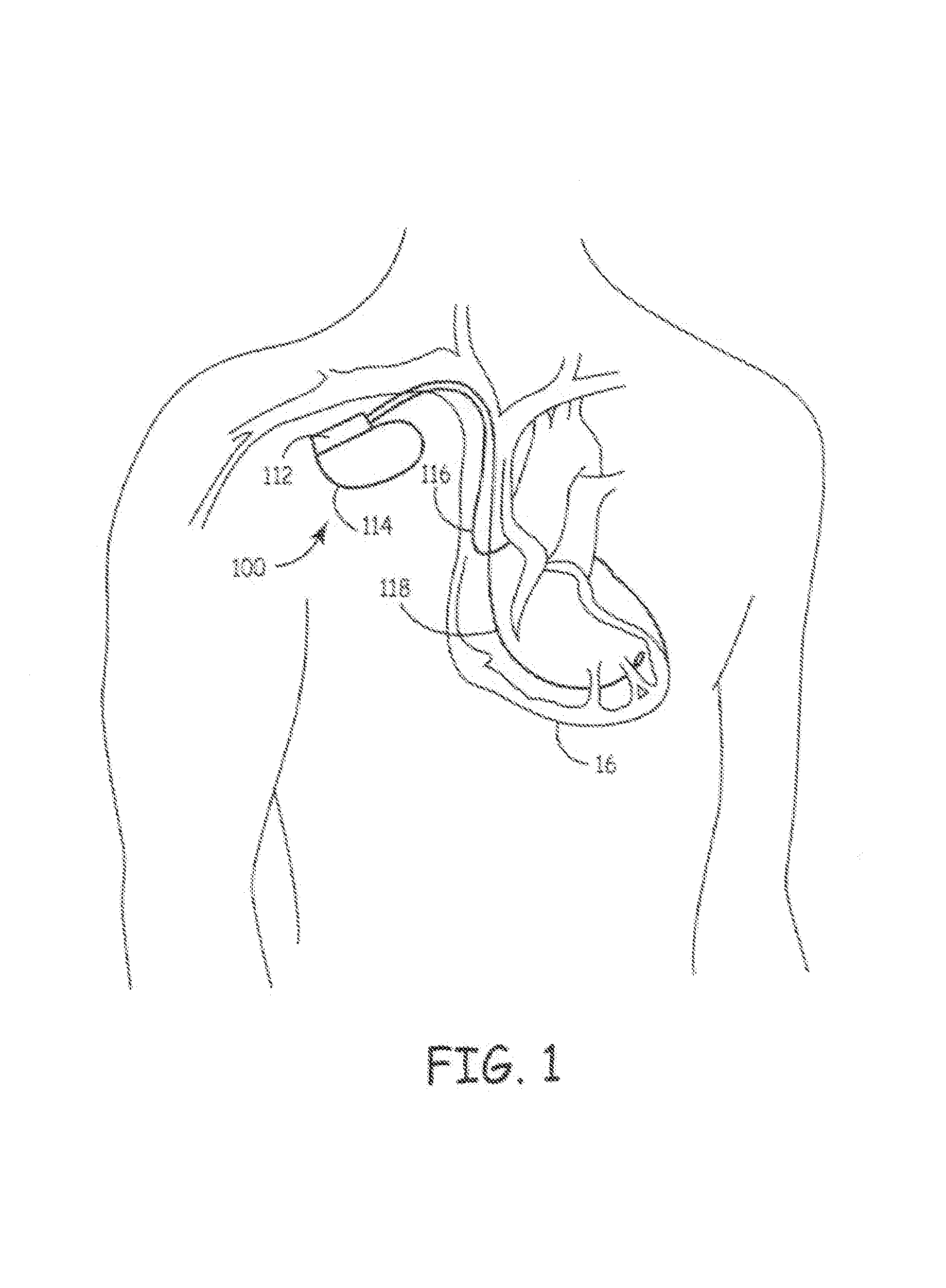
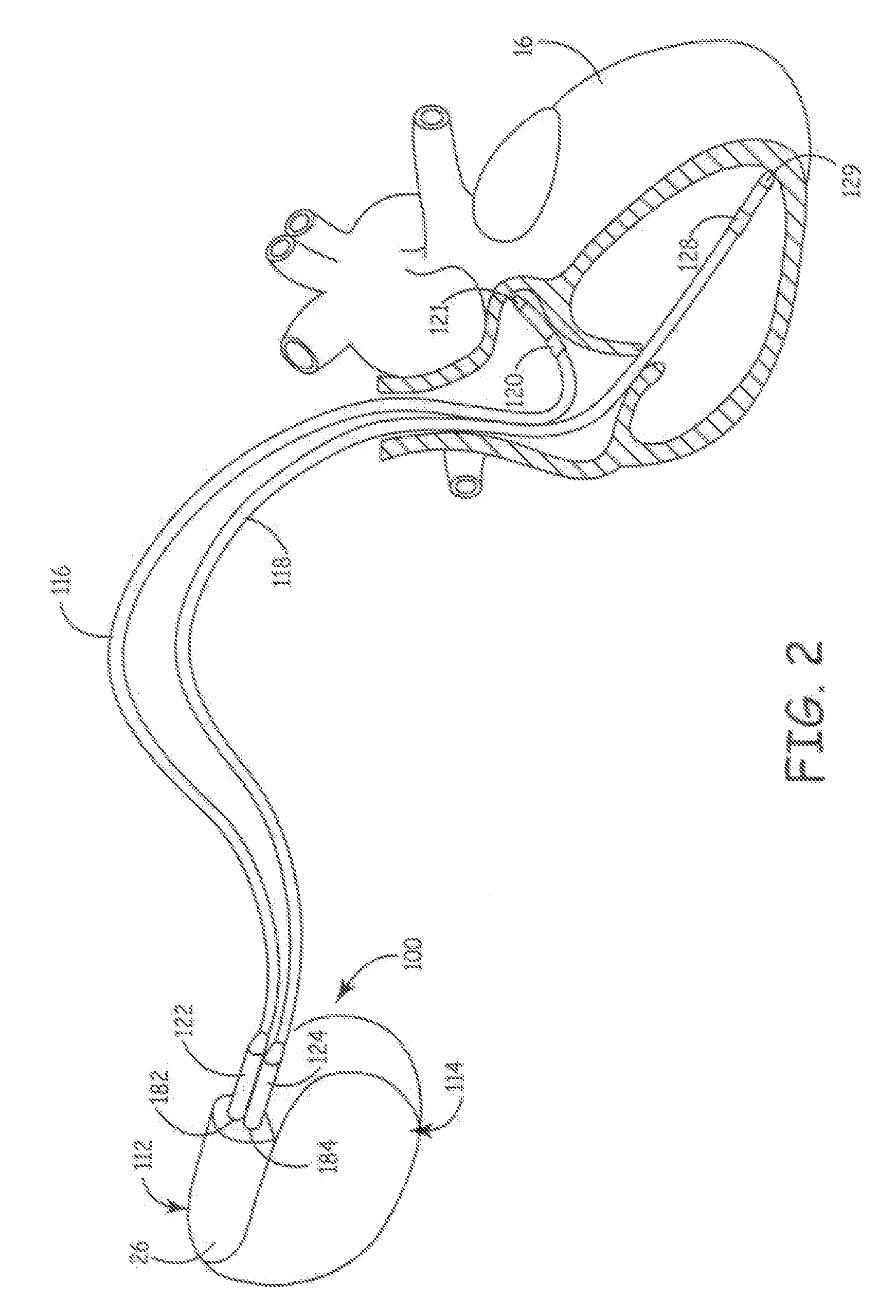
[0051]The preferred embodiments of the present invention relate to ultrasonic means for attaching or securing various components inside a pre-formed header module to thereby form a hermetically sealed enclosure. Implantable medical devices where the present invention finds application include implantable drug dispensers, IPGs (including cardiac pacemakers, pacemaker-cardioverter-defibrillators, nerve, muscle and neurological stimulators, cardiomyostimulators, etc.), implantable cardiac signal monitors and recorders and the like. Virtually all MEDTRONIC® electronic IMDs that require attachment of a hermetically sealed power supply and circuitry to an interchangeable catheter or electrical lead employ a general configuration of a hermetically sealed enclosure in conjunction with a pre-formed header module.

[0052]FIG. 1 is a simplified schematic view of an IMD 100 embodying the present invention, where an improved pre-formed header module 112 is attached to a hermetically sealed enclosu...


PUM


Abstract

The present invention generally relates to an improved implantable medical device (IMD) and more particularly to an ultrasonically weld perforated lid for an IMD to form a hermetic seal between the IMD and the perforated lid. Appropriately configured perforated lids retain one or more components within a cavity or port formed in a part of an IMD. Such lids preferably secure a pierceable resilient grommet, septum or other resilient member in a cavity or port. When an adjustment instrument, a pull tool or a syringe is temporarily inserted therethrough and later extracted, the resilient member heals (i.e., seals and / or reseals). Preferably, the resilient member abuts a mechanical stop and is compressed slightly during assembly and ultrasonic welding of the lid. The resilient member preferably has a lateral dimension like the cavity or port so that when the lid compresses the resilient member it expands slightly and contacts the interior cavity surfaces thus improving the seal.

Description

CROSS-REFERENCE TO RELATED APPLICATIONS[0001]This application is a continuation in part of U.S. patent application Ser. No. 09 / 767,796 filed Jan. 23, 2001, now abandoned which is a continuation of application Ser. No. 09 / 417,157 filed Oct. 12, 1999 now abandoned, which is a continuation of U.S. patent application Ser. No. 09 / 159,119 filed Sep. 23, 1998, now U.S. Pat. No. 6,205,358, which is a divisional of application Ser. No. 08 / 904,636 filed Aug. 1, 1997, now abandoned.[0002]The applicants hereby incorporate the contents of U.S. Pat. No. 6,205,358 to Haeg et al., which is a divisional of application Ser. No. 09 / 904,636 filed Aug. 1, 1997 and U.S. Pat. No. 5,371,514 to Wiklund et al.FIELD OF THE INVENTION[0003]The present invention relates to apparatus and methods for use in conjunction with producing an implantable medical device (IMD); and more particularly, to various means for ultrasonically welding, swaging or staking a perforated thermoplastic component to fluidly seal a manu...

Claims


Application Information

Patent Timeline
IPC IPC(8): A61N1/375
CPCA61N1/375A61N1/37512
Inventor HAEG, DANIEL C.WIKLUND, CRAIG L.KELLEY, JAMES F.
Owner MEDTRONIC INC
Learn More