Low smoke, low toxicity fiber optic cable

a fiber optic cable, low toxicity technology, applied in the field of fiber optic cables, can solve the problems of fiber optic cables subjected to conditions, requiring flawless performance in extremely demanding physical environments, loss of life and property,

Active Publication Date: 2007-03-06
JUDD WIRE
View PDF18 Cites 13 Cited by
  • Summary
  • Abstract
  • Description
  • Claims
  • Application Information

AI Technical Summary

Benefits of technology

[0020]The present invention further provides a low smoke, low toxicity fiber optic cable that comprises:

Problems solved by technology

These cables are typically employed in computerized equipment and communications applications where space and / or weight restrictions make traditional copper wiring systems inappropriate.
The commercial and military aerospace industry is a harsh testing ground for fiber optic cables, requiring flawless performance in extremely demanding physical environments.
In such environments, where even minor failures can result in loss of life and property, fiber optic cables are subjected to conditions which include destructive extremes in vibration, shock, temperature, pressure, water / chemical emersion, as well as, electromagnetic and radio frequency interference.
Unfortunately, of the limited number of materials likely to meet the smoke and toxic gas generation standards detailed above (i.e., fluoropolymers and polyimides), fluoropolymers, especially as they approach the perfluorinated state, are extremely difficult to effectively bond to any surface.
Although this cable design provides some protection for the optic fiber core, the outer jacket will shrink in the axial direction during cable manufacture and use, thereby increasing stress on the optic fiber core, which can cause the fibers to crack or break.
In addition, bonding this cable to LC connectors would be difficult where the fluoropolymers used to form the first jacketing material include perfluorinated polymers (e.g., PTFE) which, as noted above, are extremely difficult to effectively bond to any surface.
Further, it is noted that the use of steel and other metallic wires in this cable design results in a substantial increase in weight, which is objectionable in aerospace applications.
The acrylic coating material on the optical fibers, however, has a use temperature ranging from about −65° C. to about 125° C. and will degrade when the FEP buffer material, which must be melt-processed at a temperature exceeding 300° C., is extruded onto the fibers, thereby causing undesirable yellowing and even loss of integrity of the coating material.
In addition, of the embodiments described in this reference, many would fail to satisfy the rigid smoke and toxic gas emission standards noted herein while others would not bond effectively to optical connectors.

Method used


Image

  • Low smoke, low toxicity fiber optic cable
  • Low smoke, low toxicity fiber optic cable
  • Low smoke, low toxicity fiber optic cable

Examples


Embodiment Construction

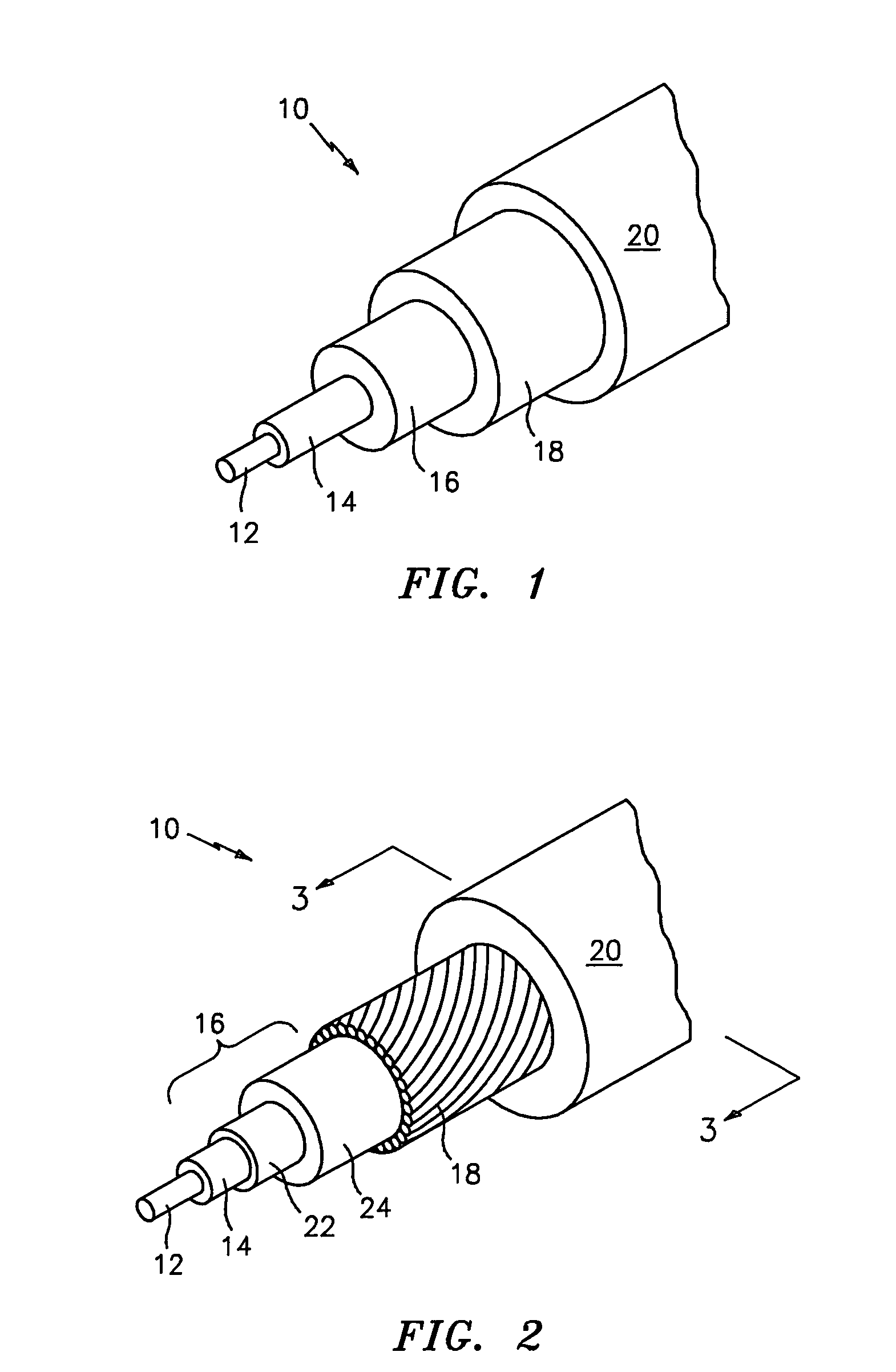
[0035]The fiber optic cable of the present invention demonstrates a combination of properties not found in conventional fiber optic cables. This unique combination of desirable properties makes the inventive cables extremely valuable in applications such as aircraft, missiles, satellites, etc. More specifically, the inventive cable exhibits low smoke and toxic gas emissions and facilitates bonding to optical connectors such as LC connectors. In a preferred embodiment, the inventive cable further exhibits improved dimensional stability in the form of reduced material shrinkage (especially reduced secondary buffer and jacket shrinkage in the axial direction) and thus reduced optical attenuation in the cable throughout a wide temperature range of from −65° C. to 135° C.

[0036]The term “low toxicity”, as used herein, is intended to mean that when tested in accordance with Boeing BSS-7324, the cable satisfies the toxicity requirements noted therein and in paragraph [0006] hereinabove.

[003...


PUM


Abstract

A low smoke, low toxicity fiber optic cable that provides an intermediate surface that facilitates bonding to optical connectors such as LC connectors, is provided. In a preferred embodiment, the inventive cable exhibits improved dimensional stability by minimizing or eliminating shrinkage stress on the optic fiber core.

Description

RELATED APPLICATION[0001]This application is a continuation in part of U.S. patent application Ser. No. 10 / 694,656, filed Oct. 27, 2003 now U.S. Pat. No. 6,898,354, which claims priority from U.S. Provisional Patent Application Ser. No. 60 / 421,665, filed Oct. 28, 2002.TECHNICAL FIELD OF THE INVENTION[0002]The present invention generally relates to fiber optic cables, and more particularly relates to a low smoke, low toxicity fiber optic cable that facilitates bonding to optical connectors such as LC connectors.BACKGROUND ART[0003]Fiber optic cables are currently being used throughout the aerospace and communications industries. These cables are typically employed in computerized equipment and communications applications where space and / or weight restrictions make traditional copper wiring systems inappropriate. Optical fiber, as a data transfer means, is known for its exceptional speed and bandwidth capability and for its ability to provide reliable communication signals.[0004]The c...

Claims


Application Information

Patent Timeline
IPC IPC(8): G02B6/44G02B6/38
CPCG02B6/3897G02B6/4483G02B6/4436G02B6/4433G02B6/4402
Inventor ANDERSON, MARK A.DOAK, JEFFREY S.GONG, GEORGEKIM, YOUNG JOONYI, JUN HONG
Owner JUDD WIRE
Why Eureka
Try Eureka