
Local oscillation signal supply method and circuit therefor

a local oscillation signal and supply method technology, applied in the direction of direction finders using radio waves, pulse techniques, instruments, etc., can solve the problems of large device scale, inability to apply, and inability to avoid phase errors caused by differences in wiring length, etc., to achieve accurate reproduction of propagation delay differences in antennas

Inactive Publication Date: 2007-03-06
NEC CORP
View PDF16 Cites 22 Cited by
  • Summary
  • Abstract
  • Description
  • Claims
  • Application Information

AI Technical Summary

Benefits of technology

[0011]It is an object of the present invention to provide a local oscillation signal supply method and circuit that solve the above-described problems and that, by means of a small-scale circuit, enable accurate reproduction of propagation delay differences in antennas of received signals that are received by way of each of a plurality of receivers.
[0014]By means of this construction, a local oscillation signal having phase and amplitude that are matched with other receivers is generated at each of the receivers, and as a result, differences in propagation delay at antennas for a received signal that is received by way of each of a plurality of receivers can be accurately reproduced.
[0017]An increase in circuit scale can be avoided by means of this type of construction.

Problems solved by technology

In a configuration in which local oscillation signals are independently supplied to receivers in this way, however, the phases of these local oscillation signals are not fixed, and such a configuration therefore cannot be applied in cases such as an adaptive array antenna system that requires the accurate detection of the phase component in the received signals of antennas.
When a local oscillation signal is received from a local oscillator as in the example shown in FIG. 1, however, the occurrence of phase error that arises from the time delays caused by differences in wiring length cannot be avoided.
As a countermeasure against the occurrence of phase error and the consequent disqualification for application in cases in which the accurate detection of the phase component is required, there exists a common synthesizer method in which oscillators are provided for each channel and local oscillation signals are distributed to each receiver, but the resulting large scale of the device is problematic.
Of the methods and circuits for supplying local oscillation signals of the above-described prior art, whether local oscillation signals are independently generated for the mixers of each respective receiver or a local oscillator is shared between a plurality of receivers as shown in FIG. 1, the lack of phase control for the input signals that are applied to the mixers results in the inability to avoid phase error of the local oscillation signals that are used in frequency conversion, and the differences in propagation delay of the received signals that are received from each of a plurality of receivers therefore cannot be accurately reproduced.
The problem therefore exists that accurate control based on phase cannot be achieved.
This inability prevents application to systems that require accurate phase control, such as an adaptive array antenna system.
The shared synthesizer method for solving this type of problem entails a complex configuration in which an oscillator is provided for each channel and local oscillation signals are distributed to each receiver, and therefore has the problem of entailing a large-scale device.

Method used


Image

  • Local oscillation signal supply method and circuit therefor
  • Local oscillation signal supply method and circuit therefor
  • Local oscillation signal supply method and circuit therefor

Examples


Embodiment Construction

[0026]We now refer to the accompanying figures to describe a working example of the present invention.

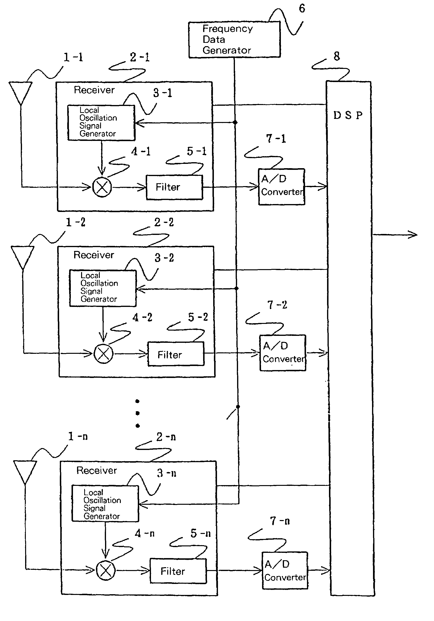
[0027]Referring first to FIG. 2, which is a block diagram showing one construction of a working example of a local oscillation signal supply circuit according to the present invention, a local oscillation signal supply circuit is shown that is constituted by: n receivers 2-1 to 2-n that are respectively provided with antennas 1-1 to 1-n; A / D (Analog / Digital) converters 7-1 to 7-n that are provided for each of receivers 2-1 to 2-n; and frequency data generator 6 and DSP (Digital Signal Processor) 8 that are provided in common for each of receivers 2-1 to 2-n.

[0028]Local oscillation signal generators 3-1 to 3-n, mixers 4-1 to 4-n, and filters 5-1 to 5-n are provided for respective receivers 2-1 to 2n. Local oscillation signal generators 3-1 to 3-n receive as input frequency data that contain a frequency component that is generated by frequency data generator 6.

[0029]This working exam...


PUM


Abstract

With the object of accurately reproducing, by means of a small-scale circuit, differences in propagation delay at antennas of received signals that are received as input by way of each of a plurality of receivers, frequency data generator 6 supplies frequency data that contain a frequency component that is synchronized in common to the plurality of receivers 2-1 to 2-n. At receiver 2-n, local oscillation signal generator 3-n, which is represented by a D / A converter, generates a local oscillation signal from frequency data that have been synchronized in common. The passing phase of a received signal that is outputted from antenna 1-n by way of receiver 1-n is thus fixed, and as a result, the phase difference of received signals that are received by DSP 8 by way of the plurality of receivers 2-1 to 2-n becomes the propagation delay difference of the received signals. As frequency data, frequency data that contain a plurality of frequency components are supplied to each receiver 2-n, and the frequency data are selected inside receiver 2-n and subjected to quadrature modulation to enable generation of local oscillation signals of differing intermediate frequencies.

Description

BACKGROUND OF THE INVENTION[0001]1. Field of the Invention[0002]The present invention relates to a method and a circuit for supplying local oscillation signals that are used in the demodulation and output by a digital signal processor of received signals of a plurality of receivers that are each connected to a respective antenna, and more particularly to a method and circuit for supplying local oscillation signals for accurately reproducing the differences in propagation delay of signals that have been received at antennas.[0003]2. Description of the Related Art[0004]Local oscillation signals are used in receivers for converting frequency. In a method and circuit of the prior art for supplying local oscillation signals, an oscillator that generates a local oscillation signal is provided for each of a plurality of receivers that are each provided with a respective antenna, and local oscillation signals are thus independently supplied to each receiver.[0005]In a configuration in which...

Claims


Application Information

Patent Timeline
Patent Type & Authority Patents(United States)
IPC IPC(8): H03K9/00H01Q3/26H04B1/14H04B1/16H04B1/26H04B7/08H04B7/12H04B15/06H04L1/06H04L27/00
CPCH04B7/084H04B1/14H04L2027/0016H04B15/06H04B7/0894H04B1/26
Inventor KAWANABE, YOSHITAKA
Owner NEC CORP
Learn More