
Flow sensor

a flow sensor and sensor chip technology, applied in the direction of volume/mass flow measurement, measurement devices, instruments, etc., can solve the problems of deterioration of heat conductivity, affecting the performance of the sensor chip, and inevitably producing small flaws on the surfa

Inactive Publication Date: 2007-03-06
YAMATAKE HONEYWELL CO LTD
View PDF6 Cites 3 Cited by
  • Summary
  • Abstract
  • Description
  • Claims
  • Application Information

AI Technical Summary

Benefits of technology

The present invention provides a flow sensor with an anticorrosion metallic diaphragm, an insulating film, and a flow rate measuring sensor. A buffer member with an intermediate linear expansion coefficient between the insulating film and the metallic diaphragm is interposed to relax the difference in thermal expansion coefficient between the insulating film and the stainless steel substrate, resulting in stable sensor detection output characteristics for a long period of time. The insulating film is preferably formed of a liquid source to make the surface flat and stabilize the sensor pattern. The metallic diaphragm is preferably formed of austenitic stainless steel or any one of hastelloy, inconel, or nickel to enhance the degree of freedom in selecting the material. The buffer member is preferably formed of silicon nitride or alumina having a similar linear expansion coefficient to achieve the same effect. The buffer member can be formed in a stepwise manner with a changing linear expansion coefficient.

Problems solved by technology

However, a sensor chip utilizing silicon has a drawback of being liable to be corroded by a corrosive gas though it is excellent in terms of sensitivity and response.
Since stainless steel is a metal, a slight flaw is inevitably produced on the surface by polishing.
However, in the case where a diaphragm provided with an oxide film and a sensor device having the same construction as that of the above-described diaphragm is used for a flow sensor, thermal characteristics such as heat conductivity degrade, so that actual use of such a diaphragm for a flow sensor is unfavorable.
Specifically, if such a diaphragm construction of pressure sensor is diverted to a thermal type flow sensor, the insulating film with low heat conductivity exerts an adverse influence on the sensitivity and response of the sensor.
As can be seen from such a difference in linear expansion coefficient between martensitic stainless steel and austenitic stainless steel, in the case where a single insulating film is formed on the surface of stainless steel, the stainless steel capable of being used as the diaphragm to relieve thermal stress due to the rising or lowering of temperature is limited to martensitic stainless steel, so that the degree of freedom in selecting material is restricted.
However, such a configuration has a drawback in that, for example, a crack is formed in the insulating film by thermal stress because of the above-described difference in linear expansion coefficient between austenitic stainless steel and silicon oxide.
Therefore, in the present situation, austenitic stainless steel cannot be used for the metallic diaphragm of flow sensor.
In a configuration in which only one layer of insulating film with a thickness that satisfies both of the requirements is formed, the difference in thermal expansion coefficient between the insulating film and the stainless steel substrate cannot be relaxed, and thus there arises a problem in that a crack is formed in the insulating film in a high-temperature environment, and hence the sensor pattern on the insulating film is broken.

Method used


Image

  • Flow sensor
  • Flow sensor
  • Flow sensor

Examples


Embodiment Construction

[0036]A flow sensor in accordance with one embodiment of the present invention will now be described.

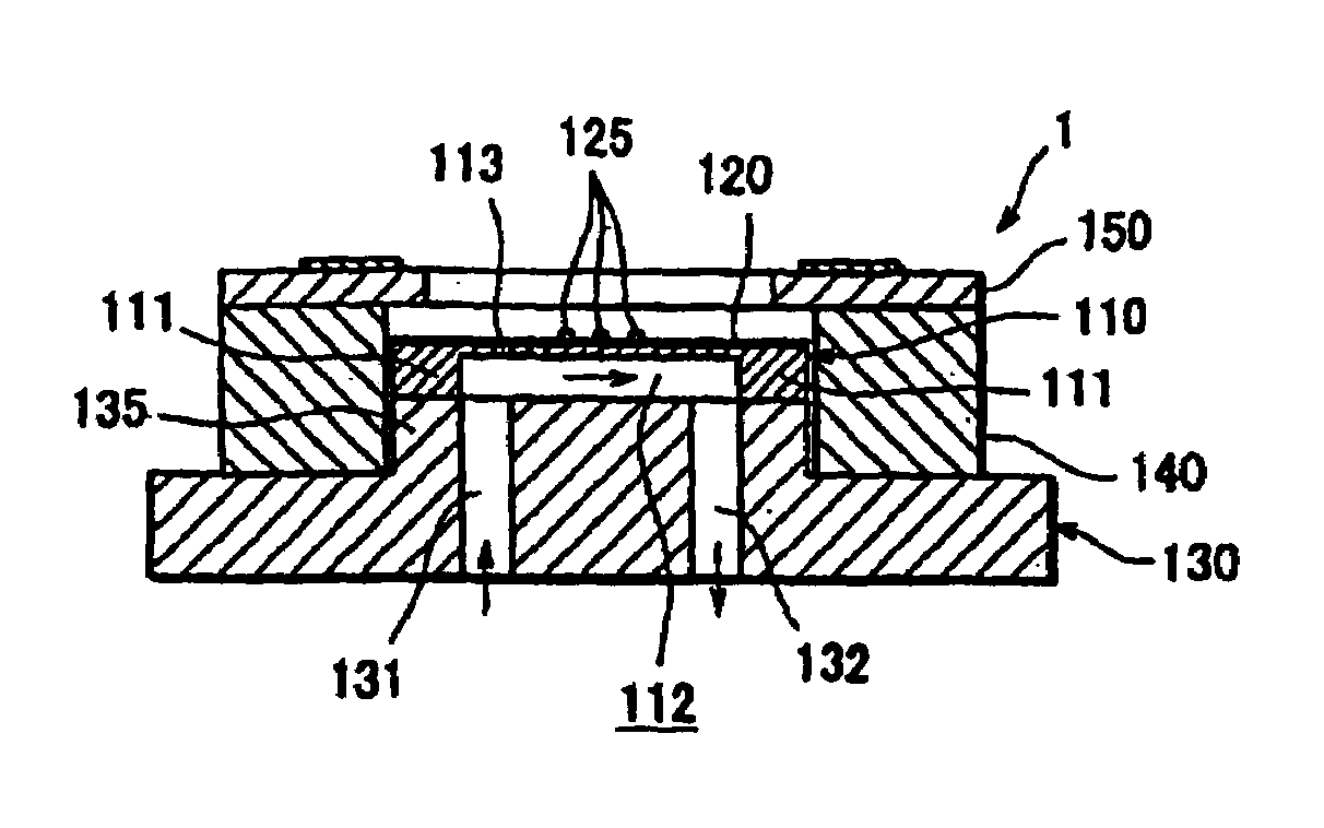
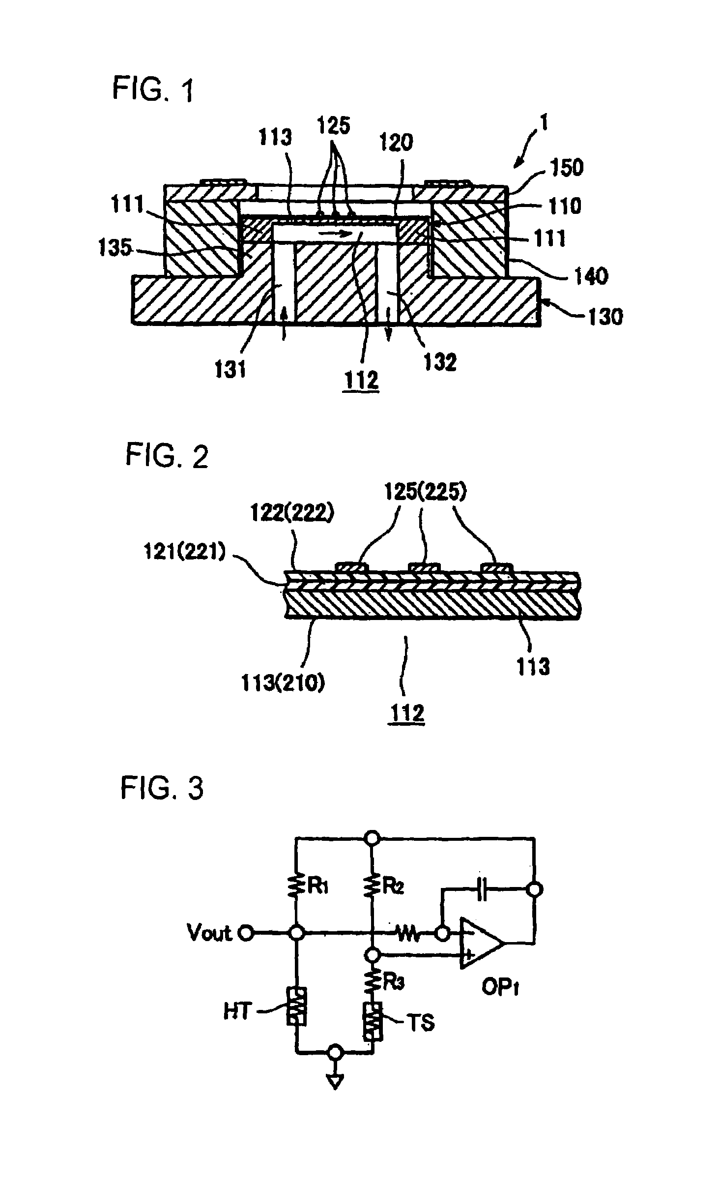
[0037]As shown in FIGS. 1 and 2, a flow sensor 1 in accordance with one embodiment of the present invention includes a metallic sensor chip 110 which has a flow path forming concave portion 112 in the back surface and is formed with flow rate measuring sensor devices 125 on the top surface via a buffer layer (buffer member) 121 and an insulating film 122 (shown in FIG. 2 only), and a flow path forming member 130 which is made of metal and forms a flow path integrally with the back surface of the sensor chip 110.

[0038]Such a flow sensor 1 is characterized in that the sensor chip 110 having a configuration different from that of the conventional sensor chip is welded to the flow path forming member.

[0039]Specifically, the sensor chip 110 is formed into a thin and slender rectangular plate consisting of stainless steel (especially, SUS316L etc.), and over the whole of one surface (top s...


PUM

PropertyMeasurementUnit
thicknessaaaaaaaaaa
thicknessaaaaaaaaaa
thicknessaaaaaaaaaa

Abstract

In a flow sensor (1) including an anticorrosion metallic diaphragm; an insulating film formed on one surface of the metallic diaphragm; and a flow rate measuring sensor formed on the insulating film, the other surface of the metallic diaphragm being in contact with a fluid under measure, between the insulating film (122) on which sensor devices (25) are formed and the metallic diaphragm, a buffer layer (121) having an intermediate linear expansion coefficient between the linear expansion coefficient of the insulating film (122) and the linear expansion coefficient of an anticorrosion metal is interposed. Thereby, the sensitivity and response of the flow sensor are improved, and also the heat resistance is improved, by which the flow sensor is made especially suitable for measuring the flow rate of a corrosive fluid.

Description

CROSS REFERENCE TO RELATED APPLICATIONS[0001]This is a U.S. national stage of application No. PCT / JP2004 / 012268, filed on 26 Aug. 2004. Priority under 35 U.S.C. §119(a) and 35 U.S.C. §365(b) is claimed from Japanese Application No. 2003-310912, filed 3 Sep. 2003, the disclosure of which is also incorporated herein by reference.TECHNICAL FIELD[0002]The present invention relates to a flow sensor for measuring flow velocity or flow rate of a fluid flowing in a flow path. More particularly, it relates to a thermal type flow sensor.BACKGROUND ART[0003]Thermal type flow sensors for measuring flow rate or flow velocity of a fluid come in two types. Specifically, there have been known a type in which a shift in spatial temperature distribution of a fluid formed by heat generation of a heater, which is a heating element, is produced via the flow of fluid, and this shift is detected by a temperature sensor (indirectly heated type) and a type in which a change in electric power or a change in ...

Claims


Application Information

Patent Timeline
Patent Type & Authority Patents(United States)
IPC IPC(8): G01F1/68G01F1/684G01F1/692
CPCG01F1/6845
Inventor IKE, SHINICHIZUSHI, NOBUHIKO
Owner YAMATAKE HONEYWELL CO LTD
Learn More