Compact folded-optics illumination lens

a technology of optical illumination and folding, applied in the field of optical illumination lenses, can solve the problems of relatively laborious and labor-intensive glueing, and achieve the effect of reducing the number of labor-intensive problems

Inactive Publication Date: 2007-02-20
LIGHT ENGINE
View PDF147 Cites 299 Cited by
  • Summary
  • Abstract
  • Description
  • Claims
  • Application Information

AI Technical Summary

Benefits of technology

[0008]In some embodiments, the present invention provides a compact folded path optical illumination lens with a means for surrounding a source and associated mechanical features or secondary optics with a gas-filled gap (typically air).

Problems solved by technology

Additionally, the gluing requires the use of a transparent adhesive and is relatively labor-intensive.

Method used


Image

  • Compact folded-optics illumination lens
  • Compact folded-optics illumination lens
  • Compact folded-optics illumination lens

Examples


Embodiment Construction

[0034]The following description of the presently contemplated best mode of practicing the invention is not to be taken in a limiting sense, but is made merely for the purpose of describing the general principles of the invention. The scope of the invention should be determined with reference to the claims.

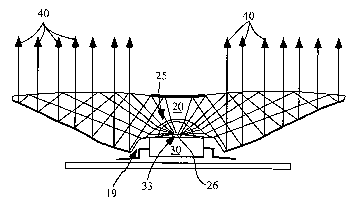
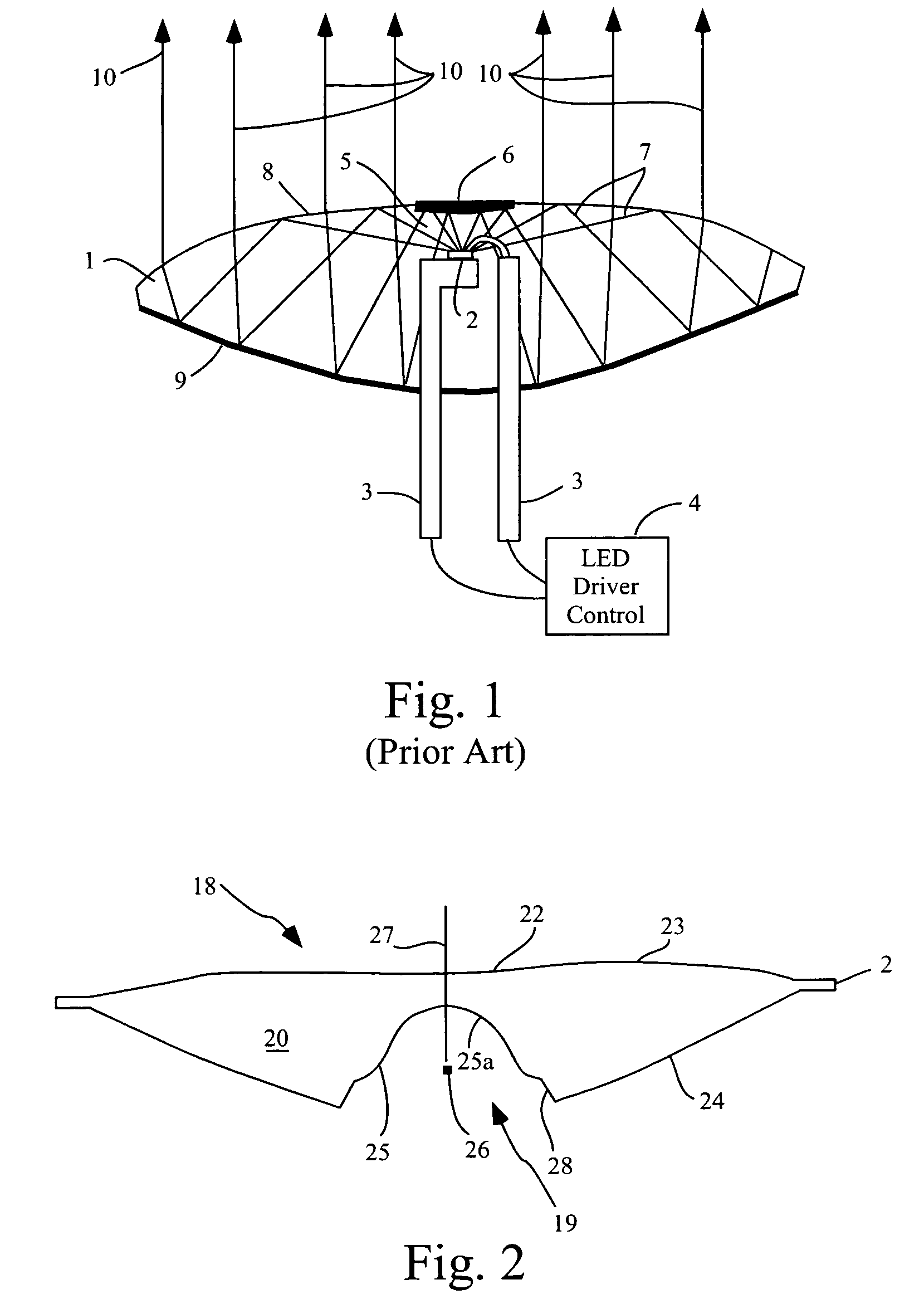
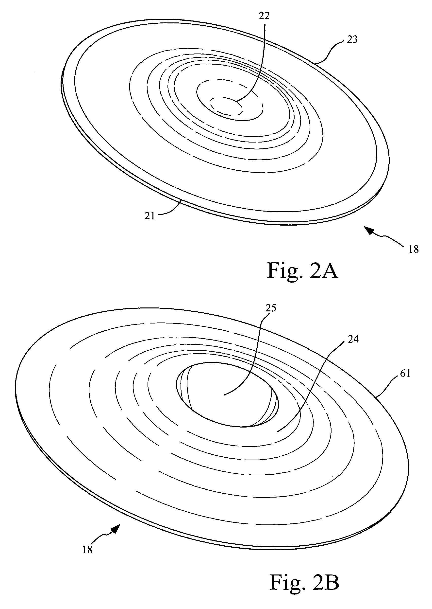
[0035]In one embodiment, an apparatus of the present invention provides a folded optical path for the efficient collimation of the optical emission of a light source, such as a light-emitting diode (LED). In one embodiment, the present invention provides for a compact optical lens providing a folded optical path. The present invention additionally provides a method for configuring and method for generating the apparatus providing the folded optical path for efficient collimation.

[0036]Previous high-efficiency non-imaging optics immerse an optical source within a lens medium. One example of a previous system that immersed an optical source is described in International Patent Applic...


PUM


Abstract

The present embodiments provide for apparatuses, and methods for manufacturing apparatuses to convert a first distribution of an input radiation to a second distribution of output radiation. The apparatus can be defined in some embodiments by generating a two-dimensional representation of three active optical surfaces including calculating a segment of first, entry and second surfaces based on first second, and third generalized Cartesian ovals, respectively, and successively repeating the calculating of the segments of the first and second surfaces, and rotationally sweeping the two-dimensional representation about a central axis providing a three-dimensional representation. In some embodiments, portion of the first and / or second surfaces can be totally internally reflective.

Description

[0001]This application is a Continuation-in-part of U.S. patent application Ser. No. 10 / 269,479, filed Oct. 11, 2002, now U.S. Pat. No. 6,896,381, and entitled COMPACT FOLDED-OPTICS ILLUMINATION LENS.BACKGROUND OF THE INVENTION[0002]The present invention relates generally to optical illumination lenses, and more particularly to folded path optical illumination lenses.[0003]Previous non-imaging folded optics utilized a light-source that had to be immersed in the dielectric medium of the lens. This immersion of the light source meant that the package containing the source, typically an LED source, is permanently glued to the lens. Additionally, the gluing requires the use of a transparent adhesive and is relatively labor-intensive.[0004]Alternatively, previous optics were generated through injection molding, requiring the LED to be sufficiently rugged to withstand the rigors of the injection molding process. In either case the optical source is immersed deep within the body of the dev...

Claims


Application Information

Patent Timeline
Patent Type & Authority Patents(United States)
IPC IPC(8): G06F17/50F21V5/00G02B17/00G02B3/02G05B15/00G06F17/10G06F7/60F21V7/00F21V13/04G02B17/08
CPCG02B19/0061G02B3/02G02B27/0012G02B19/0028F21V5/04F21V7/0091F21V13/04F21Y2101/02F21Y2101/00F21Y2115/10
Inventor BENITEZ, PABLOMINANO, JUAN C.MUNOZ, FERNANDO
Owner LIGHT ENGINE
Why Eureka
Try Eureka