
System and methods for generating spherical mosaic images

a technology of spherical mosaic and image, applied in the field of digital imaging, can solve the problems of difficult to achieve using conventional camera systems, limited field of view in both image directions, and system not well suited for high-resolution mosaicing, and achieve the effect of efficient scanning a complete spherical view of a scen

Inactive Publication Date: 2007-02-13
THE TRUSTEES OF COLUMBIA UNIV IN THE CITY OF NEW YORK
View PDF6 Cites 76 Cited by
  • Summary
  • Abstract
  • Description
  • Claims
  • Application Information

AI Technical Summary

Benefits of technology

The present invention provides a system and method for efficiently scanning a complete spherical view of a scene using a slice camera. The slice camera receives parallel rays of light and directs them onto an imaging sensor. The imaging sensor has a large field of view in one direction and a small field of view in the other direction. The system can acquire image data of the scene by interposing a mirror and a lens between the point of reception and the sensor. The image data can be used to create a spherical mosaic image of the scene. The system can also include a control unit to record the rotational position of the slice camera and a conical mirror to direct the parallel rays of light to the sensor. The system can be used in a slice camera with a large field of view and a small width of view. The imaging sensor can be a CCD imager, CMOS imager, or photographic film. The system can be used in a video system to capture a continuous spherical scan of the scene.

Problems solved by technology

A problem with conventional lenses is that they are limited in their fields of view in both image directions.
This is difficult to accomplish using conventional camera systems.
However, when a fish eye lens is used, the resolution of the image is uniformly distributed over the increased field of view and as a result, such systems are not well suited for high resolution mosaicing.
Despite their known benefits, known catadioptric imaging systems cannot capture a complete spherical view within a single image.

Method used


Image

  • System and methods for generating spherical mosaic images
  • System and methods for generating spherical mosaic images
  • System and methods for generating spherical mosaic images

Examples


Embodiment Construction

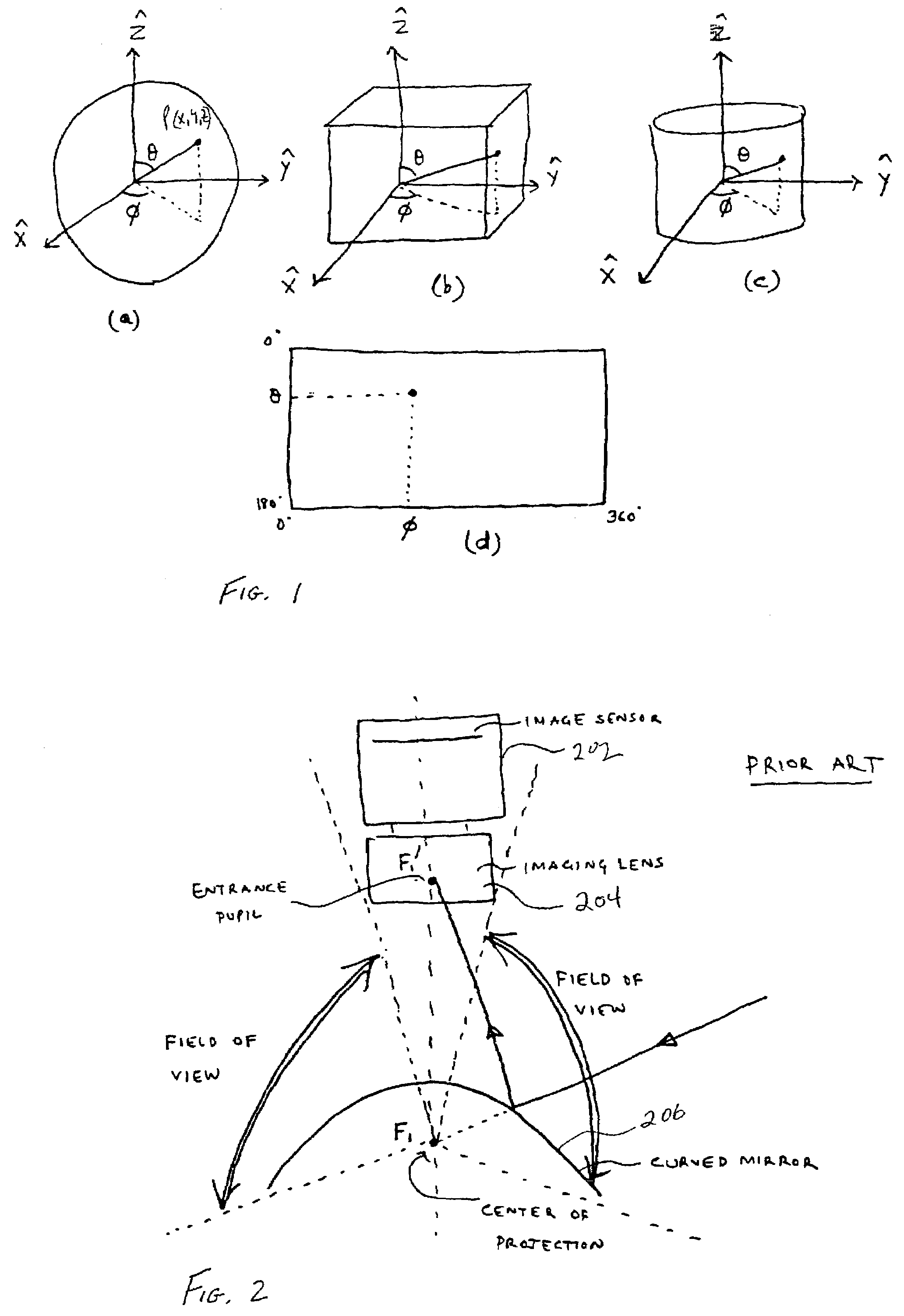
[0070]The present systems and methods are directed to the generation of omnidirectional mosaic images using acquired image “strips” or image “slices.” Referring to FIG. 7A, an image strip is a section of the spherical image having a narrow field of view which is generated by converging rays incident on the imaging system being directed onto an imaging surface. FIG. 7B illustrates the mapping of the spherical image strip onto the θ-φ) plane. As used herein, an image slice 800, which is graphically illustrated in FIG. 8A, is formed by parallel rays incident on the imaging system being acquired by an image sensor over a thin width of the spherical image. As illustrated in FIG. 8B, because the image slice is acquired from a narrow width of parallel rays, the image slice maps into a straight line 802 in the 0-φ plane. It will be appreciated that the term rays as used herein is not limited to radiation in the visible light spectrum but generally refers to high-frequency electromagnetic ra...


PUM


Abstract

Systems and methods for generating an omnidirectional mosaic image are presented in which a number of images are acquired about an axis of rotational. The images have a large field of view along the axis of rotation and a small field of view or image width in a second direction. The images can be image strips, formed from non-parallel rays directed onto an image sensor (1008), which are formed from a narrow width of parallel rays directed onto imaging sensor (1008). The images are combined to form a spherical mosaic. In the case of overlapping image strips, image combination can be performed by identifying common features in the overlapping regions and aligning consecutive image strips accordingly. A blending algorithm can then be used to improve image fidelity in the overlapping regions.

Description

[0001]The present application claims the benefit of United States Provisional application U.S. Provisional application 60 / 154,722 filed on Sep. 20, 1999 and entitled “Omnidirectional Mosaicing Using Curved Mirrors” and U.S. Provisional application 60 / 170,392 filed on Dec. 13, 1999 entitled “360×360 Mosaics”.[0002]The subject matter of this application was supported in part by a grant from DARPA ONR / ARPA MURI, Grant No. N00014-95-1-0601 and, therefore, the United States government may have certain rights to the invention.FIELD OF THE INVENTION[0003]The present invention relates generally to digital imaging and more particularly relates to the acquisition and combination of a plurality of image segments to generate spherical mosaic image data.BACKGROUND OF THE INVENTION[0004]The generation of high resolution, large field of view images is important in many areas, such as virtual reality, computer vision, robotic navigation and the like. It is generally known that mosaic images can be ...

Claims


Application Information

Patent Timeline
Patent Type & Authority Patents(United States)
IPC IPC(8): H04N5/225H04N7/00
CPCG06T3/4038H04N13/021H04N5/23238H04N5/232H04N13/211H04N23/698H04N23/631
Inventor NAYAR, SHREE K.KARMARKAR, AMRUTA
Owner THE TRUSTEES OF COLUMBIA UNIV IN THE CITY OF NEW YORK
Learn More