
Triphasic bioreactor and process for gas effluent treatment

a bioreactor and gas effluent technology, applied in the field of gas effluent treatment and air purification, can solve the problems of difficult maintenance and upkeep, lack of versatility, time-consuming bacterial acclimatization and response to perturbation periods,

Inactive Publication Date: 2007-02-13
CO2 SOLUTION
View PDF43 Cites 59 Cited by
  • Summary
  • Abstract
  • Description
  • Claims
  • Application Information

AI Technical Summary

Benefits of technology

"The present invention provides an improved apparatus for biocatalytic treatment of gas effluents. The apparatus includes a triphasic bioreactor with a reaction chamber, liquid inlet, gas and liquid outlet, and a gas bubbling means for dissolving gas into liquid. The bioreactor also has a retention device for retaining biocatalysts within the reaction chamber while releasing the solution containing the reaction product. The apparatus has advantages of biologically treating gaseous waste and optimizing gas phase dissolution into the liquid phase, while also retaining the biocatalysts within the reactor. The invention also provides a method for the biocatalytic treatment of gas effluent involving a three-step process."

Problems solved by technology

Although such biofilters have contributed to technological advances within the field of gaseous waste biopurification, the main drawbacks associated with their use are their difficult maintenance and upkeep, lack of versatility, as well as time consuming bacterial acclimation and response to perturbation periods (Deshusses et al.).
However, these are neither intended nor adequate for the cleansing of gaseous waste or effluents.
However, the adequate dissolution of gaseous waste or effluents into liquids for enzymatic conversion poses a real problem which constitutes the first of a series of important limitations which compound the problem of further technological advances in the field of gas biopurification.
Although triphasic > (GLS) reactors are commonly used in a large variety of industrial applications, their utilization remains quite limited in the area of biochemical gas treatment (U.S. Pat. No. 6,245,304; U.S. Pat. No. 4,743,545).
Such GLS treatment processes are therefore not aimed at reducing gaseous emissions.
As previously mentioned, these systems are neither intended nor adequate for the treatment of gaseous waste or effluents.
An additional problem associated with the use of these systems is the non retention of the solid phase within the reactor.
However, the biocatalyst retention problem remains largely unaddressed and constitutes another serious limitation, along with gaseous effluent dissolution, to further technological advancements.
Clogging renders them unattractive and so their use is rather limited for the retention of catalysts within reactors.
However, important drawbacks are associated with the use of enzyme immobilization, as will be discussed below.
Other major drawbacks are associated with the use of enzymatic systems.
The limited surface contact area obtainable between the dissolved gas substrate, the liquid and the enzyme's active site poses an important problem.
Hence, these systems generate significantly greater waste of input material, such as expensive purified enzymes, because the contact surface with the gaseous phase is far from optimal and limits productive reaction rates.

Method used


Image

  • Triphasic bioreactor and process for gas effluent treatment
  • Triphasic bioreactor and process for gas effluent treatment
  • Triphasic bioreactor and process for gas effluent treatment

Examples


Embodiment Construction

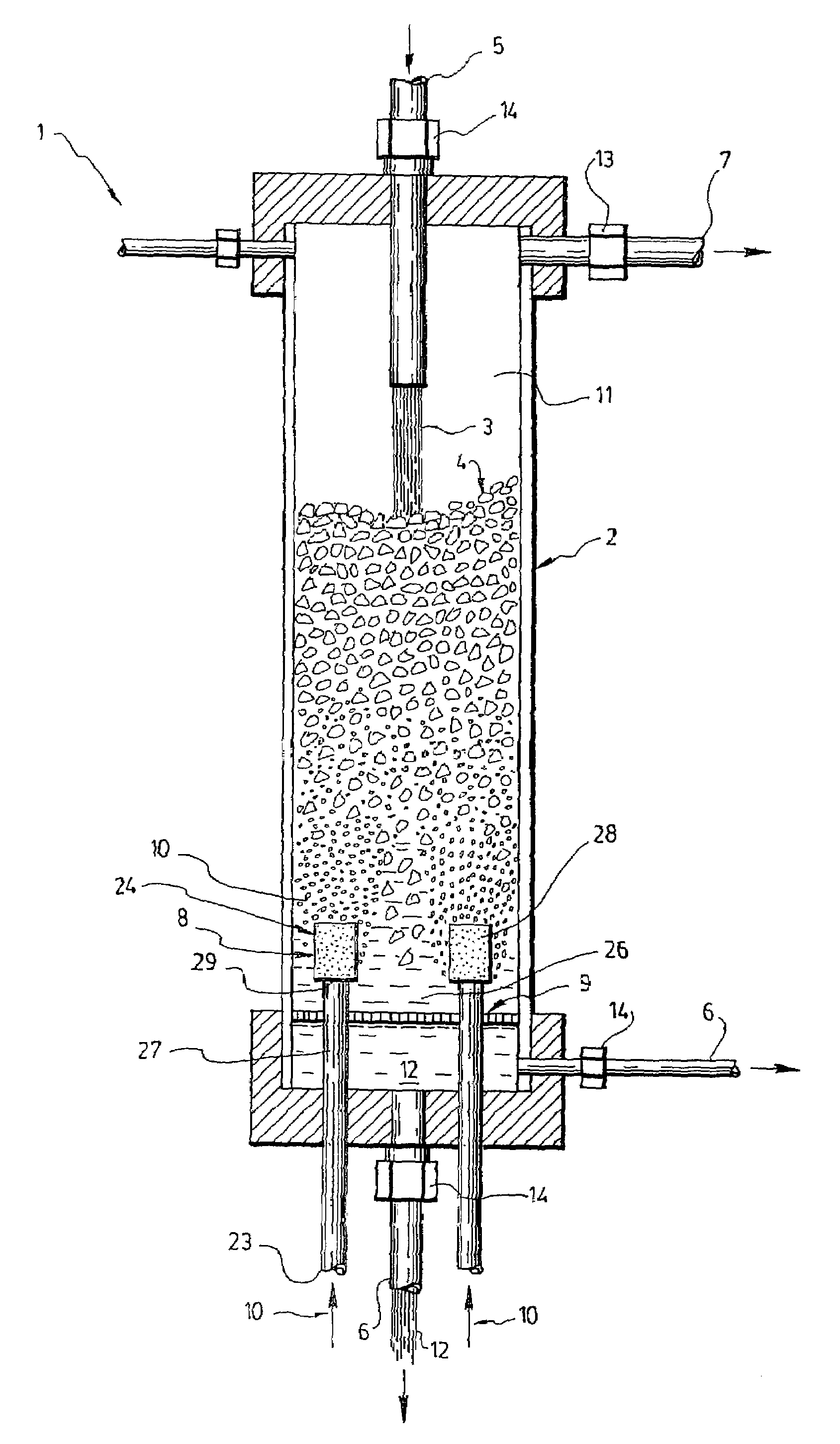
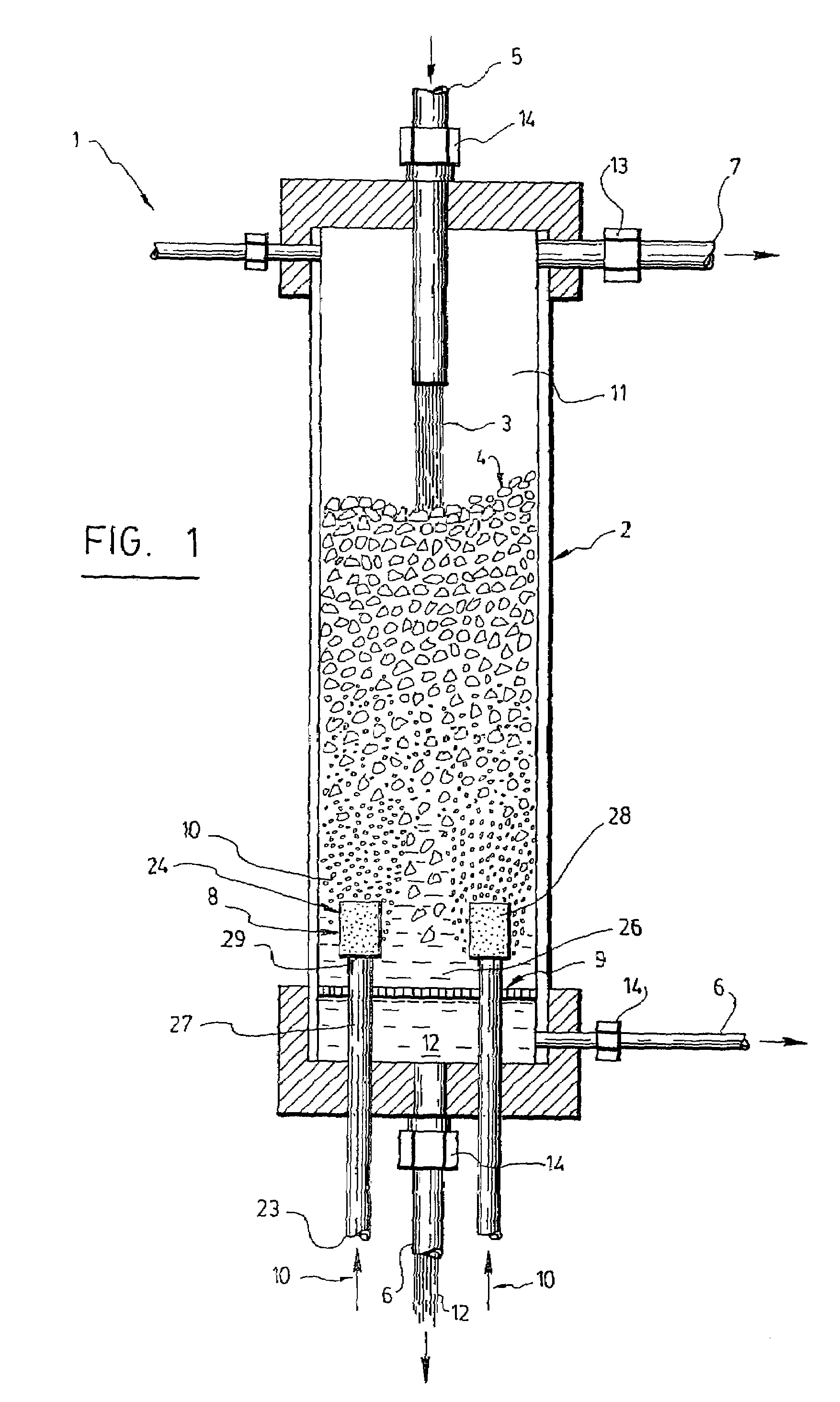
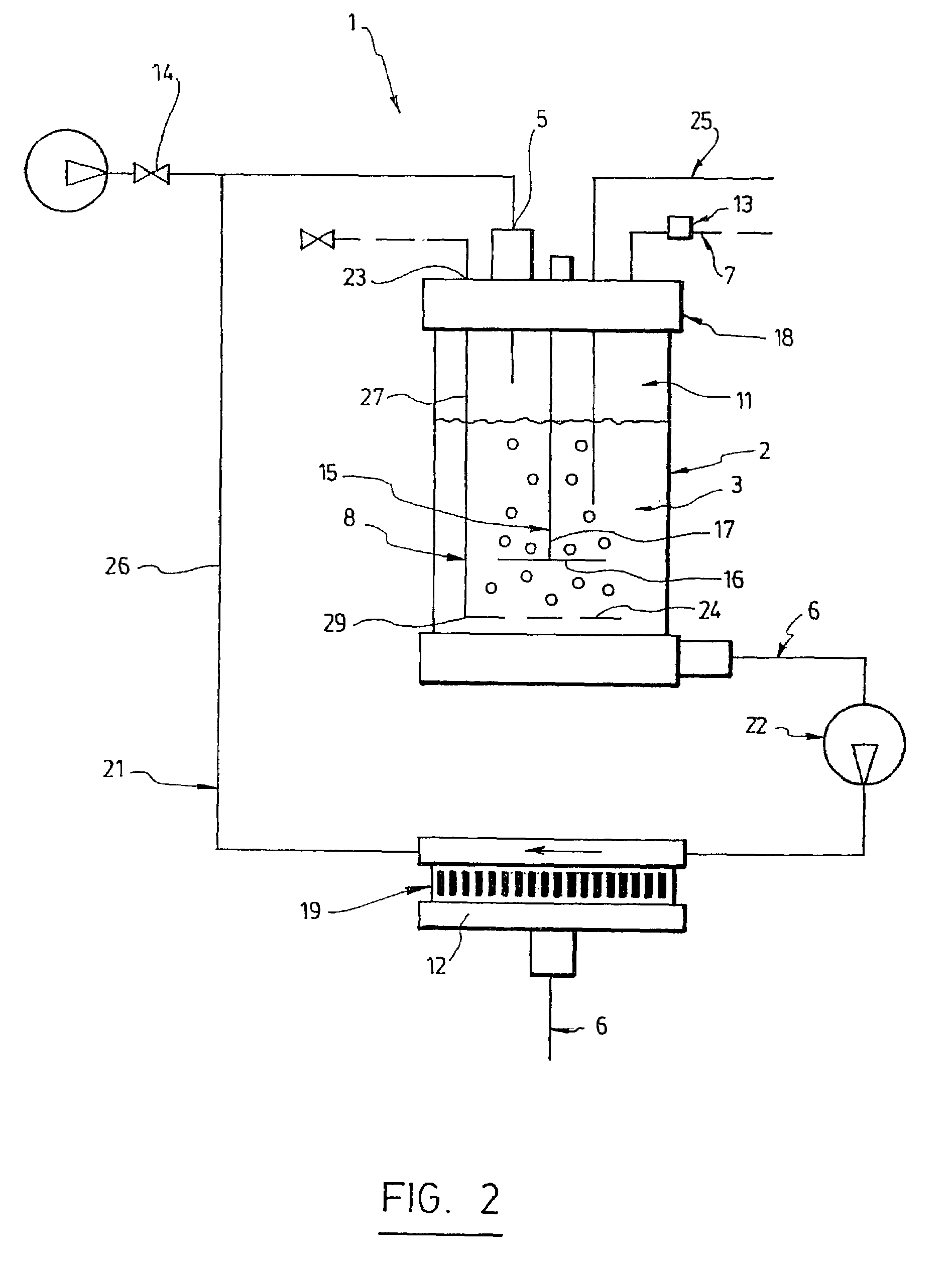
[0032]Referring to FIG. 1 or 2, the triphasic bioreactor (1) is an apparatus for physico-chemically treating a gas (10). Minimally, it features a reaction chamber (2) filled with biocatalysts (4) in suspension in a liquid (3), a liquid inlet (5) and liquid (6) and gas (7) outlets in fluid communication with the reaction chamber (2). It is worth noting that the use of the article “a” means “at least one” and hence a triphasic bioreactor according to the invention may advantageously comprise more than one reaction chamber, and / or more than one liquid and gas outlet and inlets. The liquid inlet (5) is for receiving the liquid (3) and filling the reaction chamber (2). The reaction chamber (2) is made of an appropriate material that could be glass, plastic, stainless steel, a synthetic polymer or other suitable material.

[0033]A gas bubbling means (8) and a retention device (9) are also provided. The gas bubbling means (8) is for receiving the gas (10), or gases, to be treated inside the ...


PUM

PropertyMeasurementUnit
sizeaaaaaaaaaa
molecular weightaaaaaaaaaa
diameteraaaaaaaaaa

Abstract

A triphasic bioreactor for physico-chemically treating a gas is disclosed. The triphasic bioreactor comprises a reaction chamber with a liquid and biocatalysts in suspension in the liquid, for catalyzing a reaction between the gas and the liquid to obtain a treated gas and a solution containing a reaction product. A gas bubbling means is provided in the reaction chamber for bubbling the gas to be treated into the liquid thereby dissolving the gas into the liquid and increasing a pressure inside the reaction chamber. The bioreactor further comprises a liquid inlet in fluid communication with the reaction chamber for receiving the liquid and filling the reaction chamber, a liquid outlet in fluid communication with the reaction chamber for releasing the solution and a gas outlet in fluid communication with the reaction chamber to release the treated gas. The bioreactor further comprises a retention device to retain the biocatalysts in the reaction chamber. The invention also concerns a process using the triphasic bioreactor. The triphasic bioreactor may advantageously be used for removing carbonic dioxide from a CO2-containing gas

Description

FIELD OF THE INVENTION[0001]This invention relates to the field of gas effluent treatment and air purification. More specifically, it concerns a triphasic bioreactor for the biological treatment of gaseous effluent. The invention also concerns a triphasic process for the biological treatment of gas effluent.BACKGROUND[0002]Contemporary industrial activities generate gaseous effluents containing a multitude of chemical compounds and contaminants which interfere with the equilibrium of elements in nature and affect the environment at different levels. Acid rain, the greenhouse effect, smog and the deterioration of the ozone layer are examples that speak volumes about this problem. Reduction of noxious emissions is therefore not surprisingly the subject of more and more legislation and regulation. Industrial activities and applications which must contend with strict environmental regulatory standards in order to expect any long term commercial viability, will turn more and more to biol...

Claims


Application Information

Patent Timeline
Patent Type & Authority Patents(United States)
IPC IPC(8): C12M1/12B01D53/84
CPCB01D53/84B01D53/85B01D2257/504Y02C10/04Y02E50/343Y02C10/02Y02E50/30Y02A50/20Y02C20/40
Inventor PARENT, CARMENDUTIL, FREDERIC
Owner CO2 SOLUTION
Learn More