
Wheel chair drive apparatus and method

a technology for driving apparatus and wheel chairs, applied in the direction of electric propulsion mounting, wheelchair/patient conveyance, transportation and packaging, etc., can solve the problems of cumbersome installation and transportation, large space required for storage of the unit, and substantial obstacles to mobility and everyday tasks. , to achieve the effect of reducing the space required for storage, quick and easy, and improving traction

Inactive Publication Date: 2007-02-06
MIDAMERICA ELECTRONICS CORP
View PDF38 Cites 20 Cited by
  • Summary
  • Abstract
  • Description
  • Claims
  • Application Information

AI Technical Summary

Benefits of technology

The solution provides a more efficient and compact motorized wheelchair drive system that offers better mobility, longer battery life, and precise control, enabling easier transportation and operation in various environments, including tight spaces.

Problems solved by technology

Substantial obstacles to mobility and everyday tasks of living continue for those who are disabled and bound to wheel chairs.
These devices are cumbersome in their operation, installation and transportation.
This creates difficulty in packing, as for example in the trunk of an automobile.
Weight represents a substantial hardship, particularly for the elderly person, whose caregiver is commonly an elderly spouse.
Prior art devices are also bulky and do not collapse into a small enough package for convenient transportation, again as in the trunk of a car.
The prior art units do not have batteries that are easily removable.
This shaft is not movable, and accordingly obstructs ingress and egress from the wheel chair.
The unadjustable vertical control shaft makes simple tasks difficult, such as pulling the chair up to the table, as for reading or a meal.
These units are also difficult to install for a caregiver.
They are prohibitively difficult for the disabled individual themselves to install.
The prior art devices have inefficient drive trains that use drive chains and further necessitate inefficient gearing and small drive wheels.
Their systems are only 35% efficient.
This inefficiency leads to a choice between either large, heavy batteries or smaller batteries that use an inordinate amount of power with an appreciably shorter charge life.
In operation, the prior art units use small drive wheels that too readily transfer shock from minor impediments, such as a brick floor.
Even slightly larger objects, such as a cobble stone street, become virtually impossible to traverse.
Further shortcomings of prior art devices include a lack of control precision when operating the wheel chair driver, particularly in tight spaces.
Although it is known that wheel chairs are often used in enclosed or crowded spaces such as dining rooms, elevators, work places and the like, prior art drive units are only capable of travel at walking speed, without offering slower speeds for precise handling.
The high torque and control sensitivity desirable for maneuvering in a crowded space at slow speeds is currently unavailable.

Method used


Image

  • Wheel chair drive apparatus and method
  • Wheel chair drive apparatus and method
  • Wheel chair drive apparatus and method

Examples


Embodiment Construction

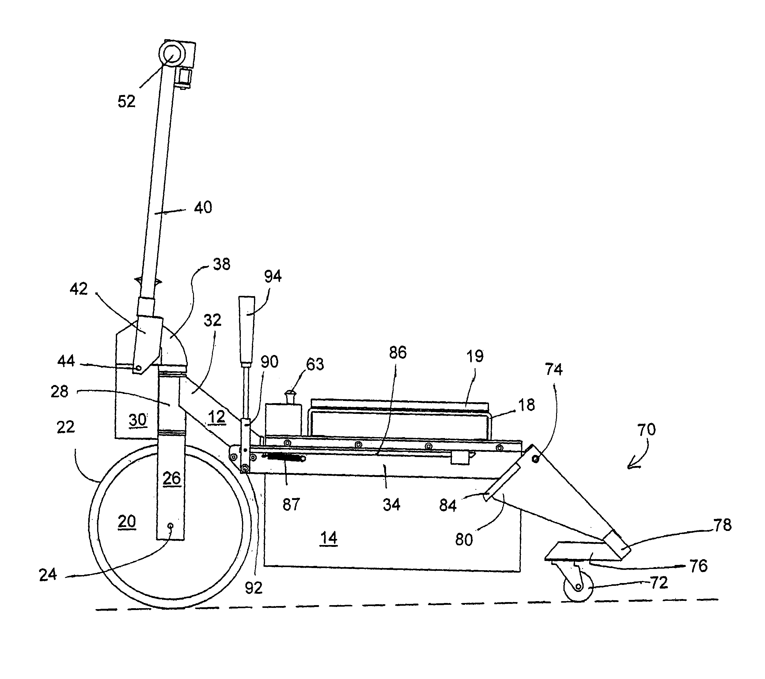
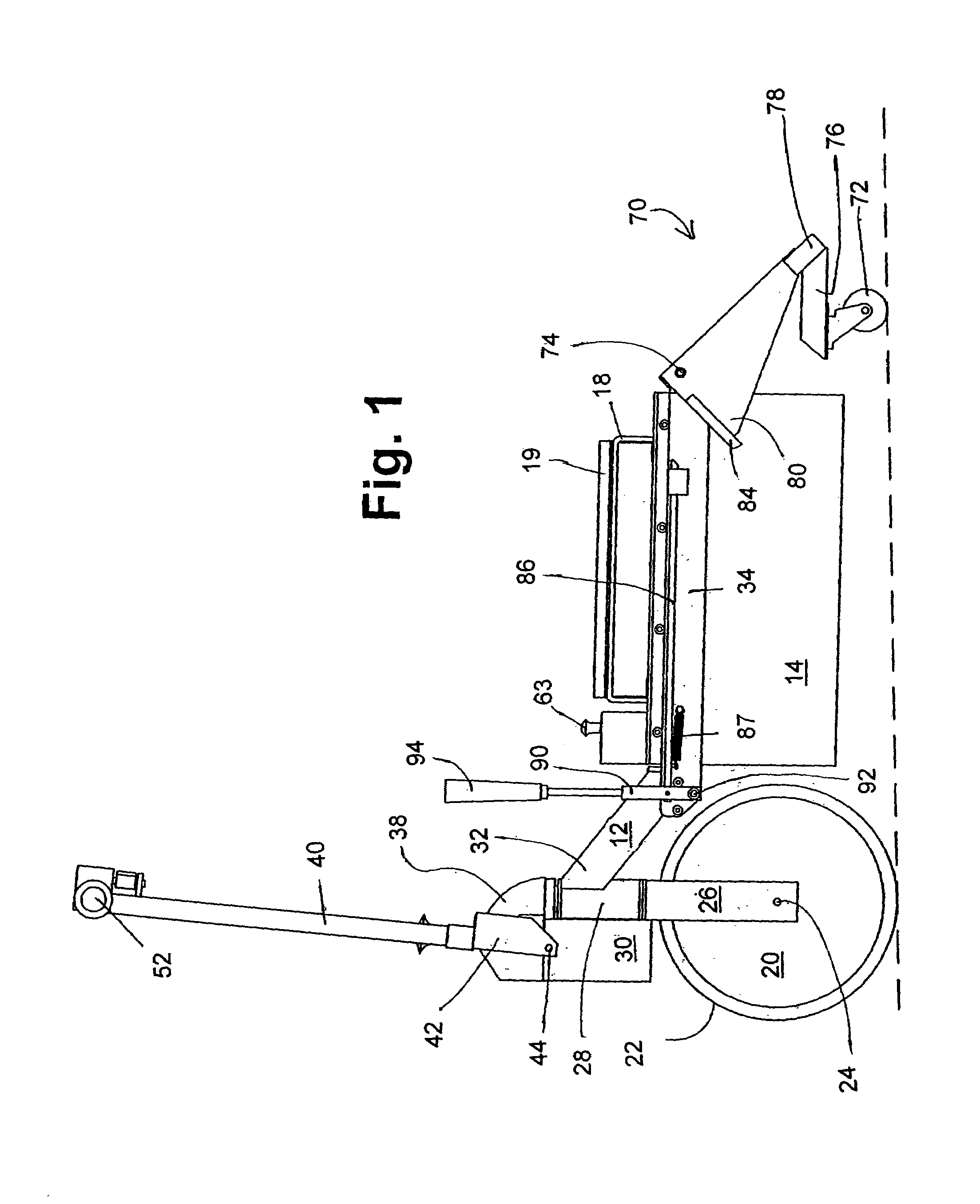
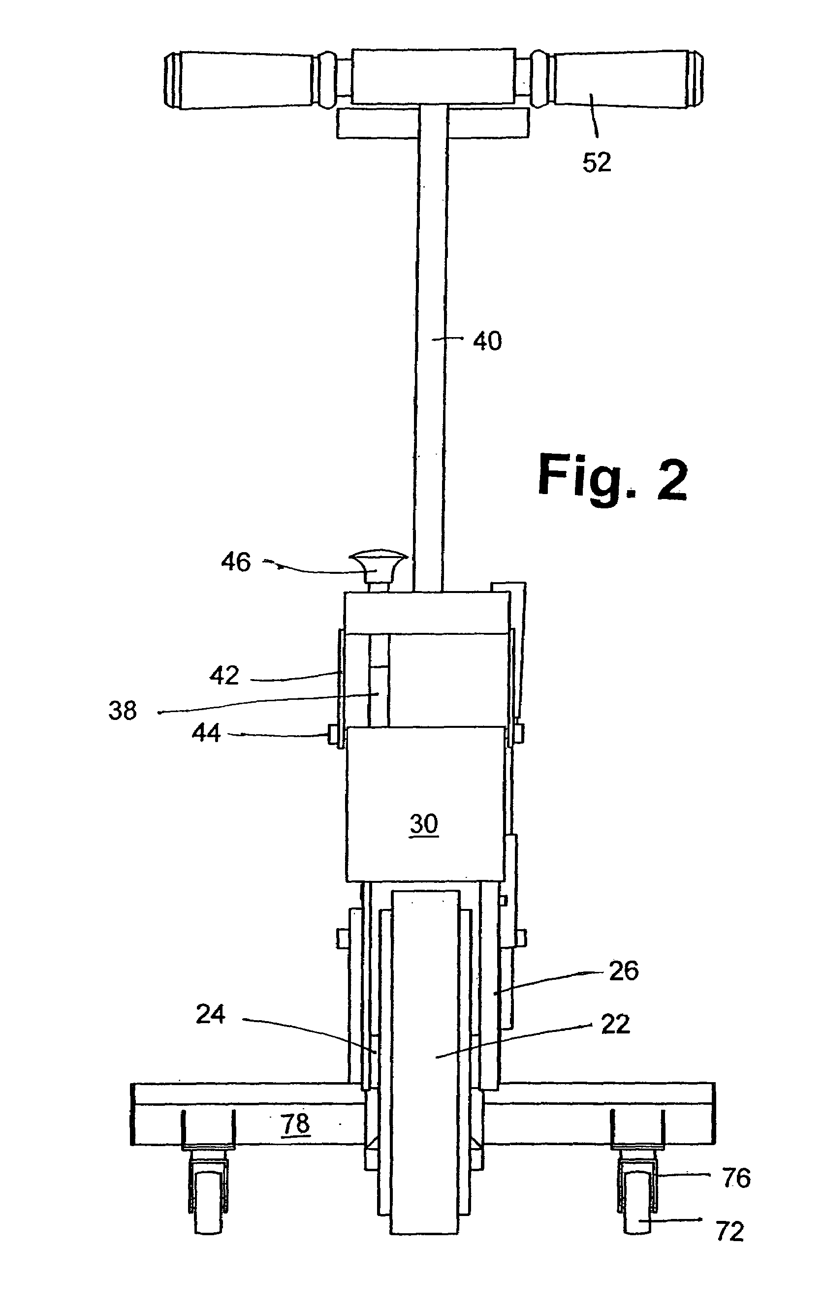
[0076]Referring to the accompanying drawings in which like reference numbers indicate like elements, FIGS. 1, 2, 3, 4 and 5 are side, front, side and top views, respectively, of the wheel chair motor drive of the present invention. FIG. 15 shows the motor drive apparatus 10 engaged with a wheel chair.

[0077]The wheel chair motor drive apparatus 10 is comprised of a frame 12 and, when assembled, a battery housing 14.

[0078]Drive wheel 20 comprises the housing for a high torque electric motor (not shown) within the wheel in the depicted embodiment. The wheel 20 is also the rotor of the electric motor, as well as the casing for the stator housed within it. The motor and wheel 20 are coaxial in the depicted embodiment. The wheel 20 also has a friction surface or tread 22 disposed circumferentially thereon.

[0079]The drive wheel axle 24 supports drive wheel forks 26. The forks 26 are fixedly attached to a fork bearing journal 28 which is substantially vertical in the depicted embodiment.

[00...


PUM


Abstract

A control system for a powered wheel chair drive modulates a pulse power delivery signal such that power is delivered gradually at throttle positions corresponding to a low speed, and power is delivered more rapidly at throttle positions corresponding to a higher speed.

Description

CROSS-REFERENCE TO RELATED APPLICATIONS[0001]This application is a continuation-in-part of U.S. application Ser. No. 10 / 832,939, filed Apr. 27, 2004.STATEMENT REGARDING FEDERALLY SPONSORED RESEARCH OR DEVELOPMENT[0002]Not Applicable.APPENDIX[0003]Not Applicable.BACKGROUND OF THE INVENTION[0004]1. Field of the Invention[0005]The present invention is in the field of motorized wheel chairs, particularly, electric motor drivers attachable to standard wheel chairs to provide power to drive them.[0006]2. Related Art[0007]Substantial obstacles to mobility and everyday tasks of living continue for those who are disabled and bound to wheel chairs. There is a continuing need to make mobility for the wheel chair bound more reliable and convenient.[0008]Motor drives for standard wheel chairs exist in the prior art. U.S. Pat. No. 5,494,126 to Meeker and U.S. Pat. No. 5,050,695 to Kleinwolterink Jr. describe motor drive units that may be attached to standard push wheel chairs.[0009]U.S. Pat. No. ...

Claims


Application Information

Patent Timeline
Patent Type & Authority Patents(United States)
IPC IPC(8): H02P7/29A61G5/04A61G5/10A61G7/08B62D1/00H02P7/288
CPCA61G5/047A61G2203/36A61G2005/1051A61G5/10A61G5/1051
Inventor KIDD, WILLIAM W.JENKINS, JOHN P.
Owner MIDAMERICA ELECTRONICS CORP
Learn More